|
|
|
Step 1 Going to the Junkyard
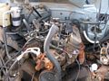
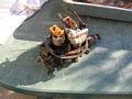
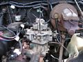
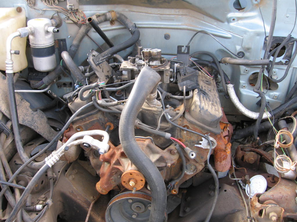
We're looking for a late 80's or early 90's GM vehicle with a 4.3L V6 engine. If you can, find your stuff from a Chevy full-size pickup truck.
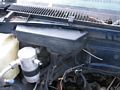
Here's the Chevy 1500 pickup we got ours from. |
|
|
You can tell it's the correct vehicle by deciphering it's VIN. The 8th character
of the vin will indicate the engine size. A "Z" indicates an EFI 4.3L v6.
The 10th character will tell the year of the vehicle. A "J,K,L,M or N" is the
desired letter, J=88,K=89,L=90,M=91, and N=92. You can use this
link as a
guide. |
|
|
|
|
|
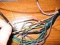
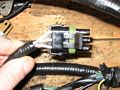
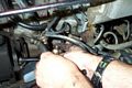
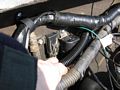
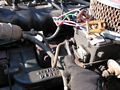
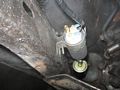
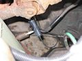
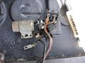
This is how the wiring harness goes into the cab of a Chevy truck. Just remove
the 2 bolts and it will come out. The computer plugs are about 1' inside the
cab from this point. You need to take the entire harness. |
|
|
|
|
|
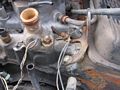
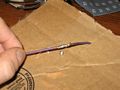
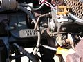
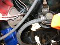
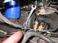
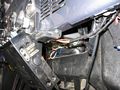
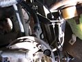
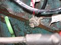
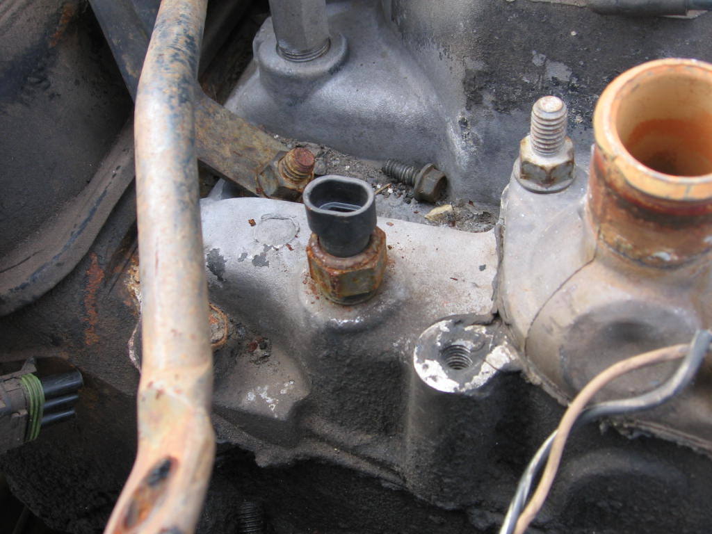
This is the temp sensor. It will be located on the front of the intake
manifold. Take this. |

|
|
|
|
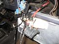
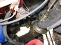
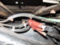
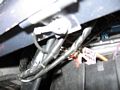
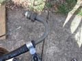
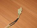
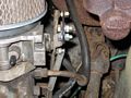
This is the knock sensor. Its located on the driver side of the block under the
exhaust manifold. Just pull it because you don't have to worry about the plug
end, its going to get spliced into pin c14 of the comp anyway to eliminate the
use of a knock sensor.
|

|
|
|
|
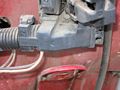
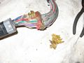
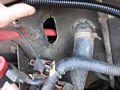
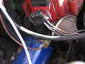
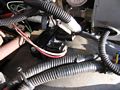
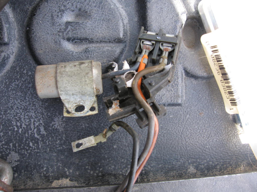
This is the other side of the harness at the fuse block. Remove the center bolt
(like on a CJ) and it will separate into 3 pieces, you want the bottom most
harness, it will be part of the TBI harness.
|
|
|
|
|
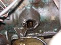
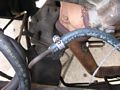
Sensor grounds, unbolt from the intake.
|
|
|
|
|
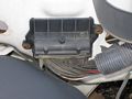
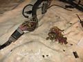
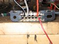
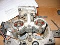
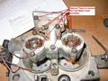
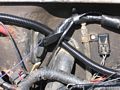
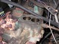
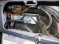
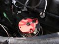
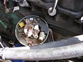
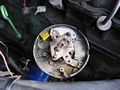
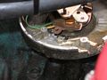
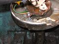
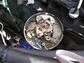
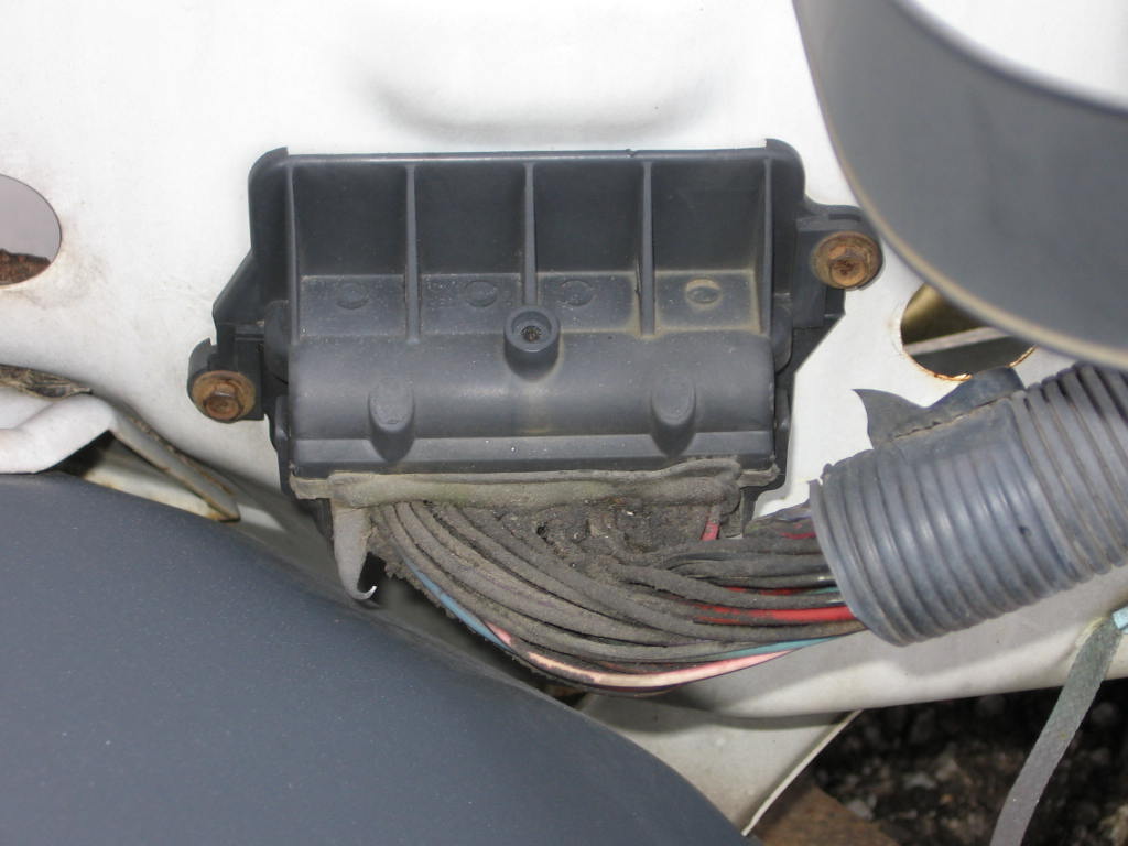
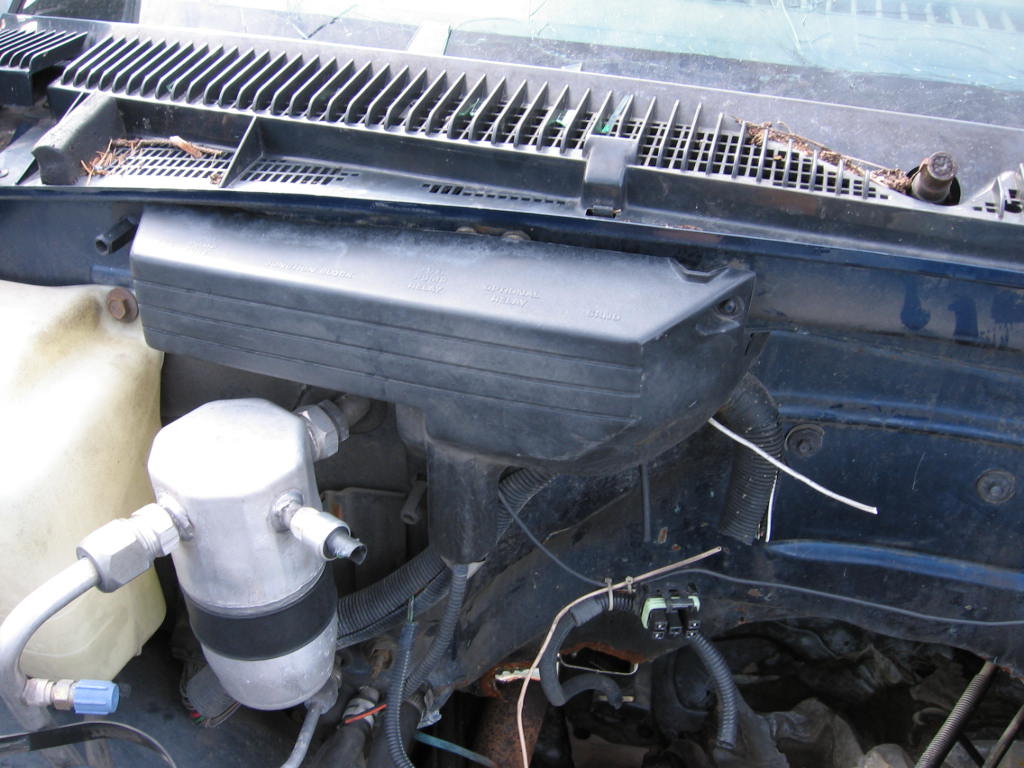
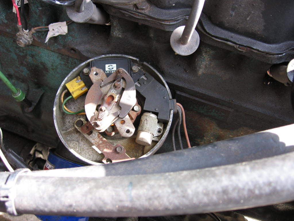
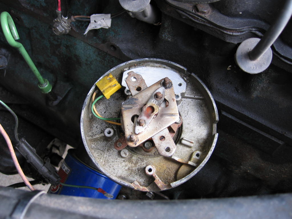
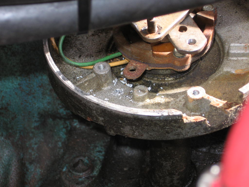
Under the plastic cover is the fuel pump relay, and the junction block for the
wires of the TBI harness.
|
|
|
|
|
|
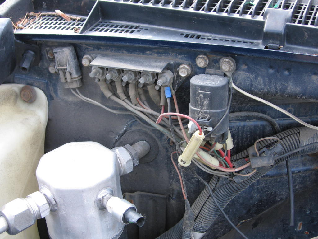
What you will see when you remove the plastic cover. |

|
|
|
|
|
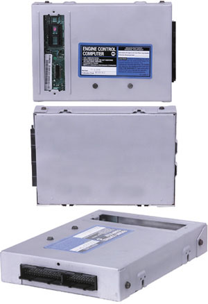
The computer was already picked from this vehicle as well as all the other
possible donor vehicles. We found one on Ebay instead. If
you're lucky to find the computer behind the glove box of your donor, open it up
(there are a half dozen tiny screws) and make sure the ECM is model #1227747 or
1228746. |

|
|
|
|
|
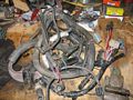
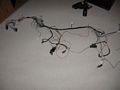
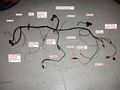
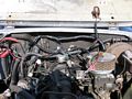
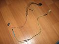
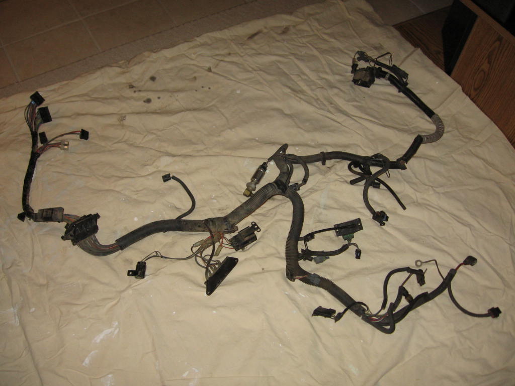
Step 2 Figuring out the Wiring Harness Here is the GM harness out of
the vehicle. It seems like a lot but it really isn't that bad. |
|
|
|
|
|
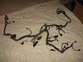
GM harness laid out ready to get to work. We need to cut out the wires
from the loom that we don't need. |
|
|
|
|
|
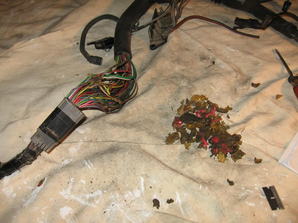
First thing to do is to remove the connector to the firewall and all the epoxy
under it that keeps it water tight. |
|
|
|
|
|
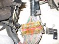
To get the epoxy off use a razor blade carefully to score it following the
wires. Then use a pair of pliers to peel the epoxy back. It is more of an
brittle epoxy (could be from age) so it will crack if you bend it right. Just
keep working at it it will come off. There is also a red piece of plastic that
separates about every 5 wires encased in the epoxy. It is open on the top and
one piece on the bottom (like a comb) and the wires go in between the upright
pieces of it. If you score the epoxy deep enough to the wires and then pull on
the wires it will break through. This was actually the hardest part of the
harness and took the longest.
|
|
|
|
|
Free at last. All the epoxy plastic removed from the harness.
Another way to remove the epoxy is to use a heat gun and just melt the goo
(technical term) right off. Hold it over a trash can when you do it.
Still another way is to just make your wire length adjustment right there.
So just cut the whole harness in half and then put your splices in there when
you have the length of each wire set in the vehicle.You can get a harness
from a Chevy S10 and it won't require melting epoxy off the wiring harness. It
has a big rubber grommet cast around the wiring. It can be kept together. You
can then add or subtract length to the harness in your engine compartment but
the inside stuff will work fine. |
|
|
|
|
|
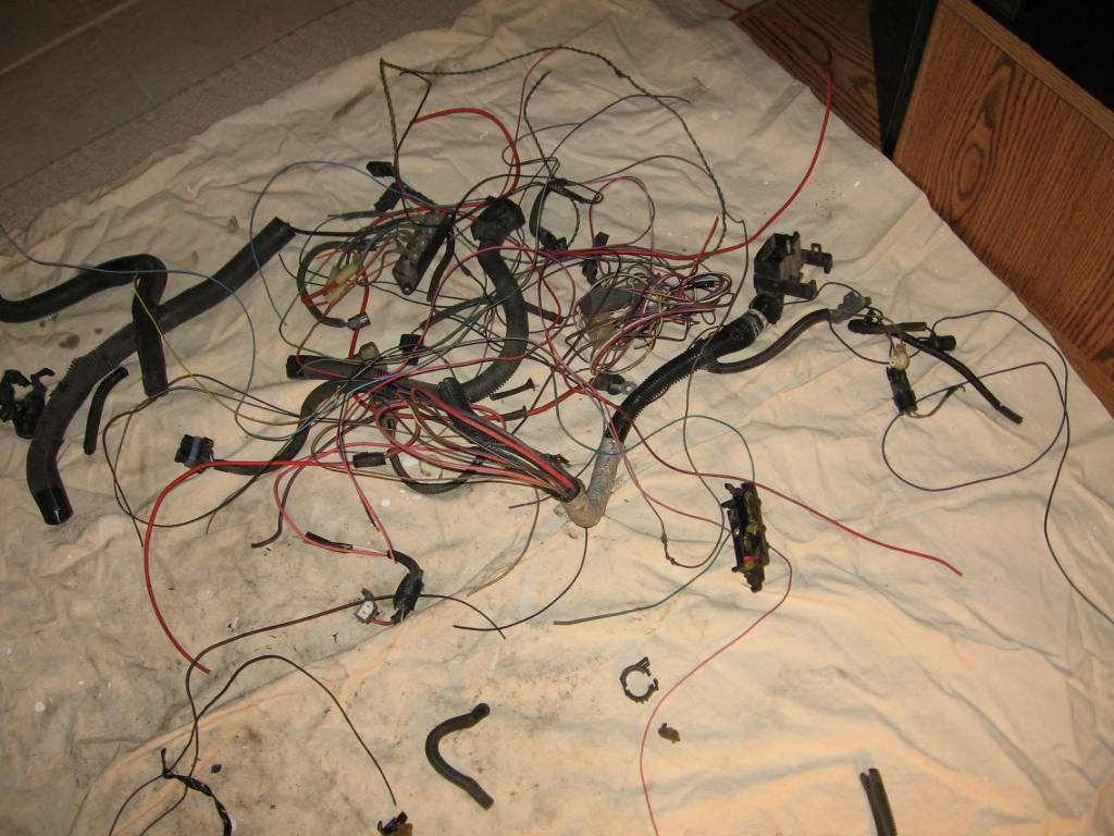
GM harness leftovers. This is all the wires and split loom that will be
removed, and is not needed. |

|
|
|
|
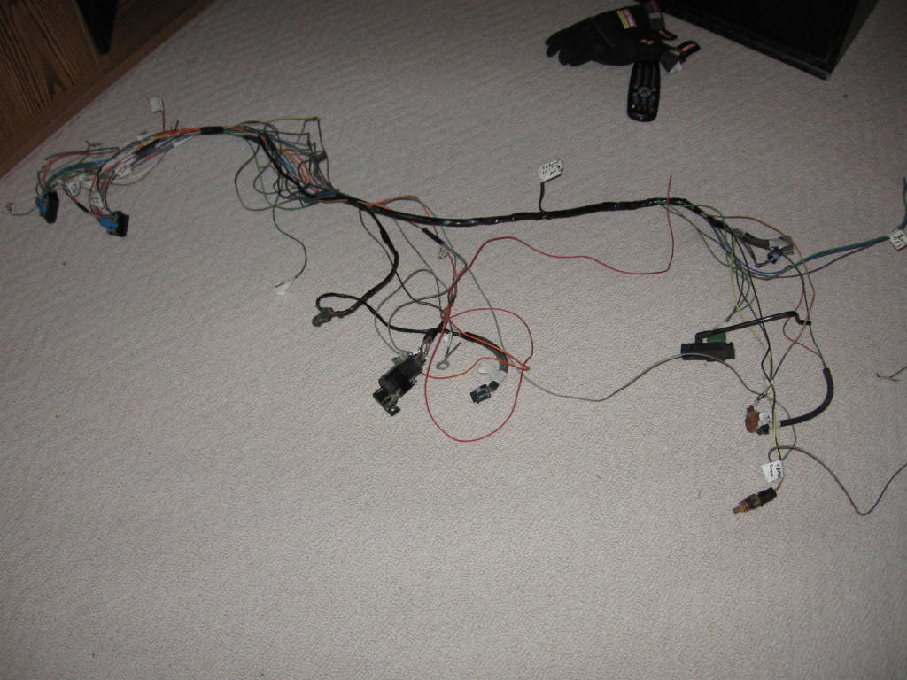
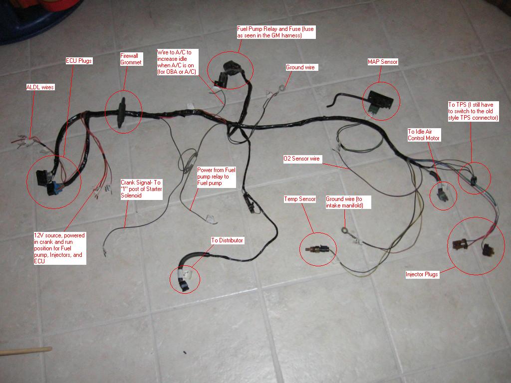
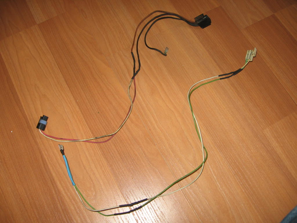
This is the harness that you will end up with.
Brief description from left to right:
-ECM plugs a/b and c/d with a few short wires that you will have to extend and
connect for the aldl connector, ses light, and system ground.
-Dist plug if you choose to have the ecm control the spark (I will be using this
for the HEI dist)
-Fuel pump relay, and fuse
-Starter connector (crank signal)
-Fuel pump 12v, and ECM 12v
-2 grounds
-O2 sensor wire
-Sensors- MAP, Temp, IAC, TPS,
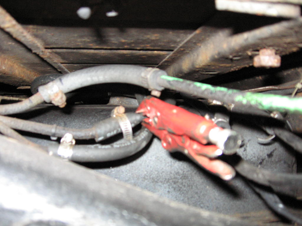
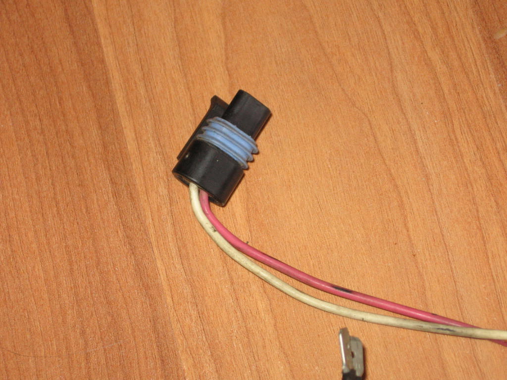
-Injector wires, Note: the blue and green go to the ecm, while the red and white
(which connect to a white plug, not the ecm plug, inside the cab of the gm
vehicle) got to a switched 12v source.
Here's a great
link that
explains every single ping in the harness |
|
|
|
|
|
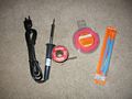
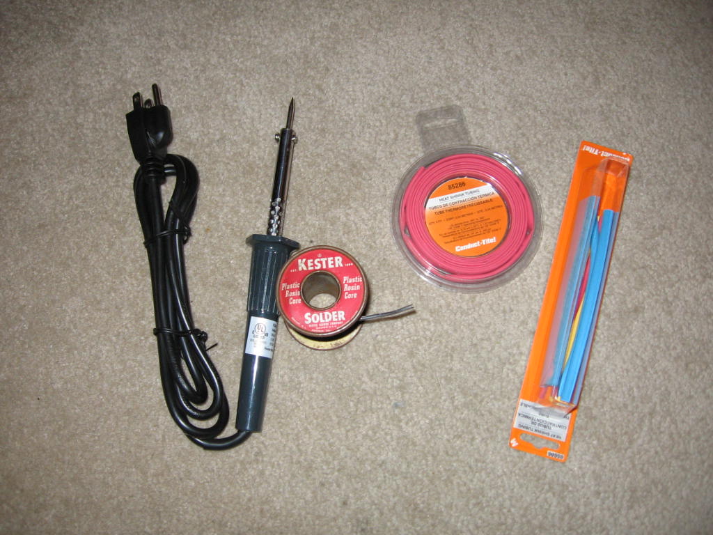
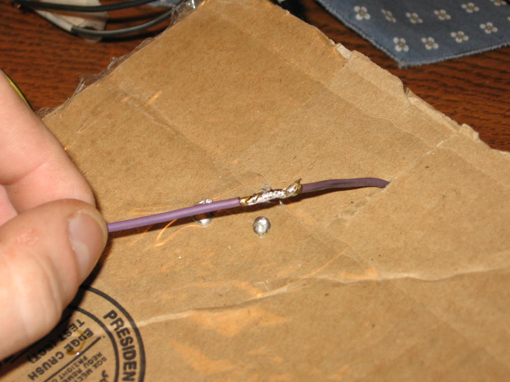
To properly complete the harness you will need a good soldering iron or gun,
resin core solder, and heat shrink tubing (use the tubing with the matte finish
from Auto Zone, instead of the shiny finish from Radio Shack, it doesn't melt). |
|
|
|
|
|
Make sure you get a good solder joints. |
|
|
|
|
|
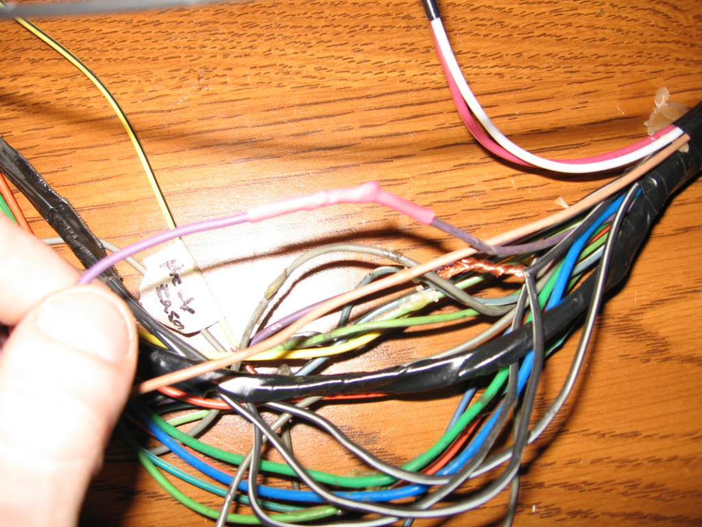
Now you can put the heat shrink tube over the solder joint to protect it. Make
sure you put the heat shrink tubing over the wire before you solder, and keep it
a good distance away from where you are soldering because the heat can
prematurely shrink it in the wrong spot. To shrink the tubing in the correct
spot use a lighter, heat gun or blow-dryer. |
|
|
|
|
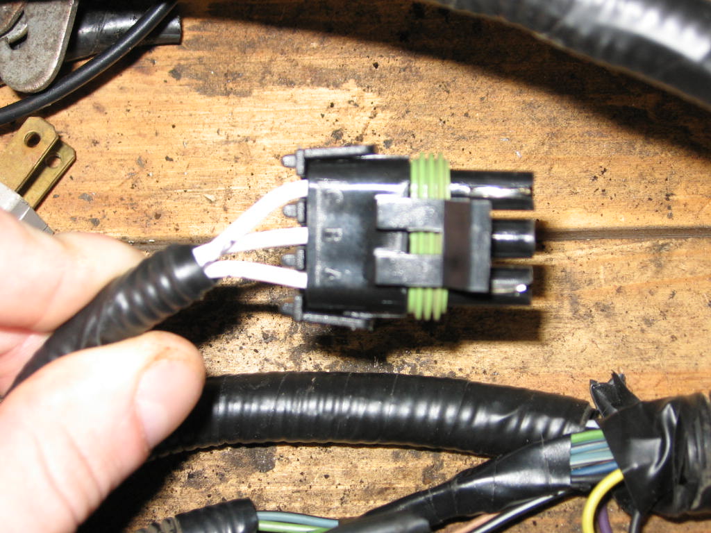
Here is the back of the ALDL plug. The orange and white/black tracer are from
the ECM and carry data. The black/white tracer is a ground and the red is the
optional fuel pump test wire.
|
|
|
|
|
Here is my finished TBI Harness. I labeled the wires to give an idea of what
goes where. Notice how I kept the plugs that went to certain parts of the
engine bay close together.
|
|
|
|
|
|
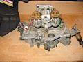
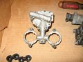
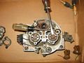
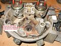
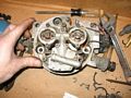
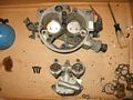
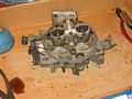
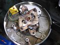
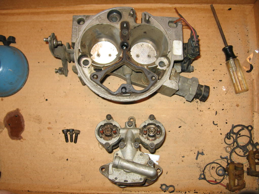
Step 3 Rebuilding the Throttle Body Unit This is how I got the TB from the yard. It was really dirty, as the engine it
was on had a lot of blow-by. I cleaned it up with carb cleaner and a
toothbrush. (**Make sure to wear safety glasses because carb cleaner isn't fun
to get in your eye) |
|
 |
|
|
|
|
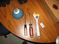
This is what you will need to take the TB apart. It is a flathead screw driver,
size 20 torx screwdriver (or socket), razor blade to remove old gasket material,
adjustable wrench, and oil to lightly coat o-rings for the injectors. |
|
|
|
|
|
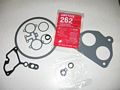
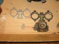
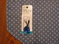
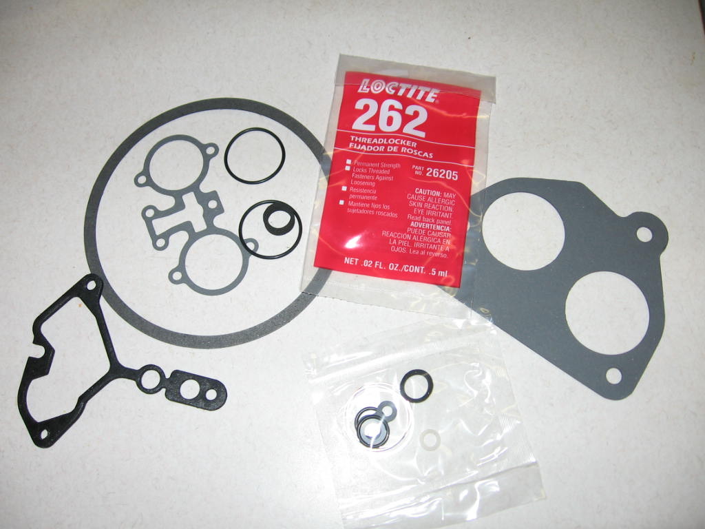
This is the TB gasket set I picked up from Autozone. It is part #96-3013A from
GP Sorenson |
|
|
|
|
|
First remove the injector plugs, and the rubber fitting under them. |
|
|
|
|
|
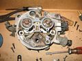
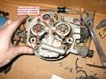
Remove the 8 bolts marked to remove the Fuel Meter Cover Assembly off the Fuel
Meter Body |
|
|
|
|
|
Fuel Meter Cover Assembly Cover removed |
|
|
|
|
|
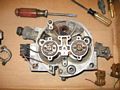
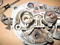
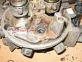
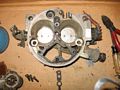
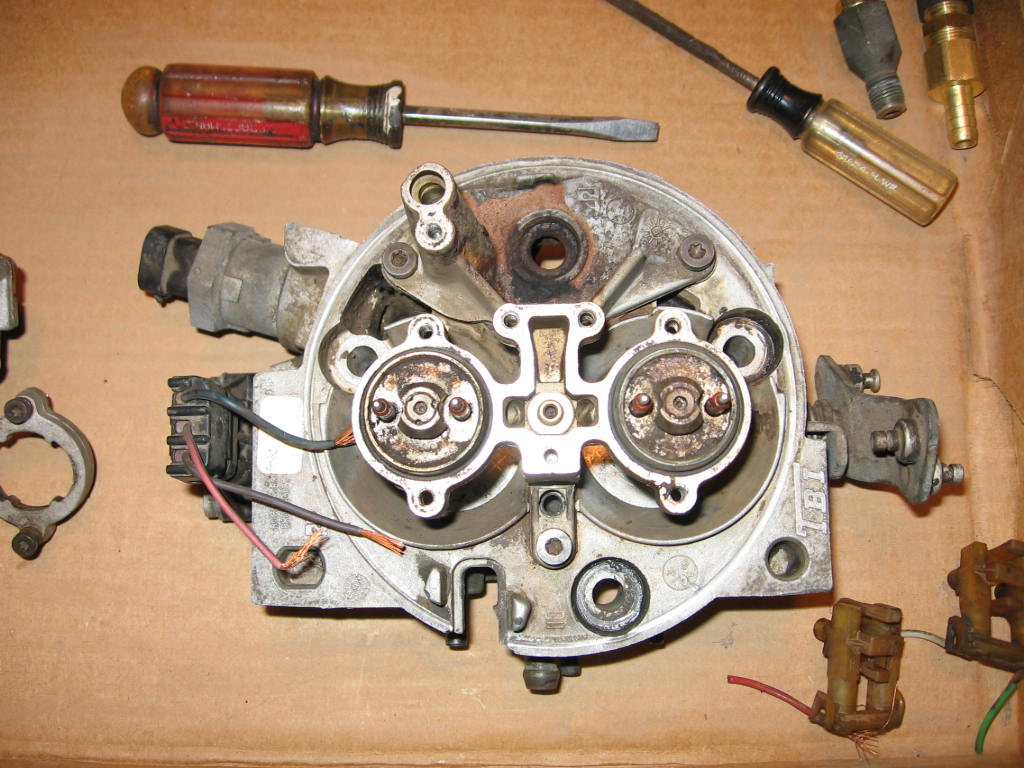
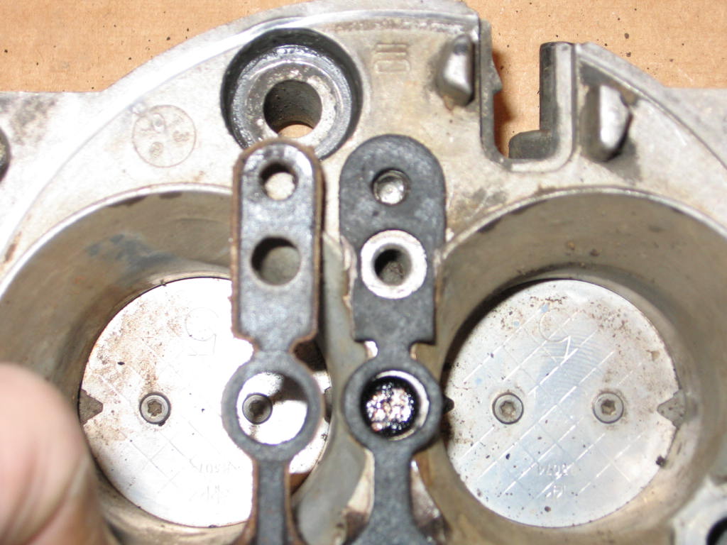
This is what you will see. |
|
|
|
|
|
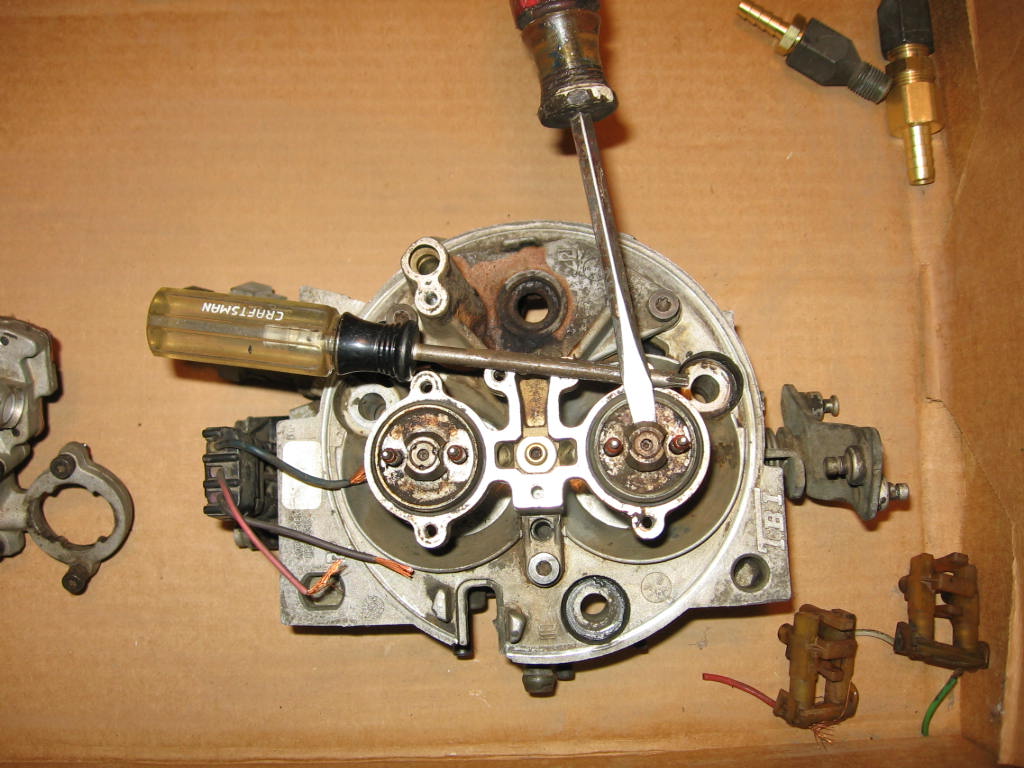
To remove an injector place a screwdriver on the Fuel Meter Body, and use that
to act as a fulcrum so you can place a screwdriver on it and lift an injector
up. |
|
|
|
|
|
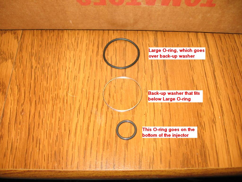
After you remove the injector, remove the large O-ring and the back-up washer,
they just sit in place. |
|
|
|
|
|
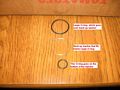
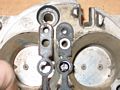
This is the order of that goes on in the injector port. Small O-ring goes on
the bottom of the injector, back-up washer then goes in the injector port, and
the large O-ring goes on top of that. Lightly coat the O-rings with oil. |
|
|
|
|
|
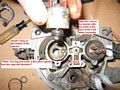
Injector ready for reassembly into the fuel meter body. Notice the O-ring on the
bottom of the injector. Also the Large O-ring is inside the Injector port, and
the back-up washer is under that. To install the injector make sure the "lug"
on the injector is facing the direction of the notch in the base of the injector
port, as noted in the picture. **Note the notch and lug of the other
injector face the opposite direction. |
|
|
|
|
|
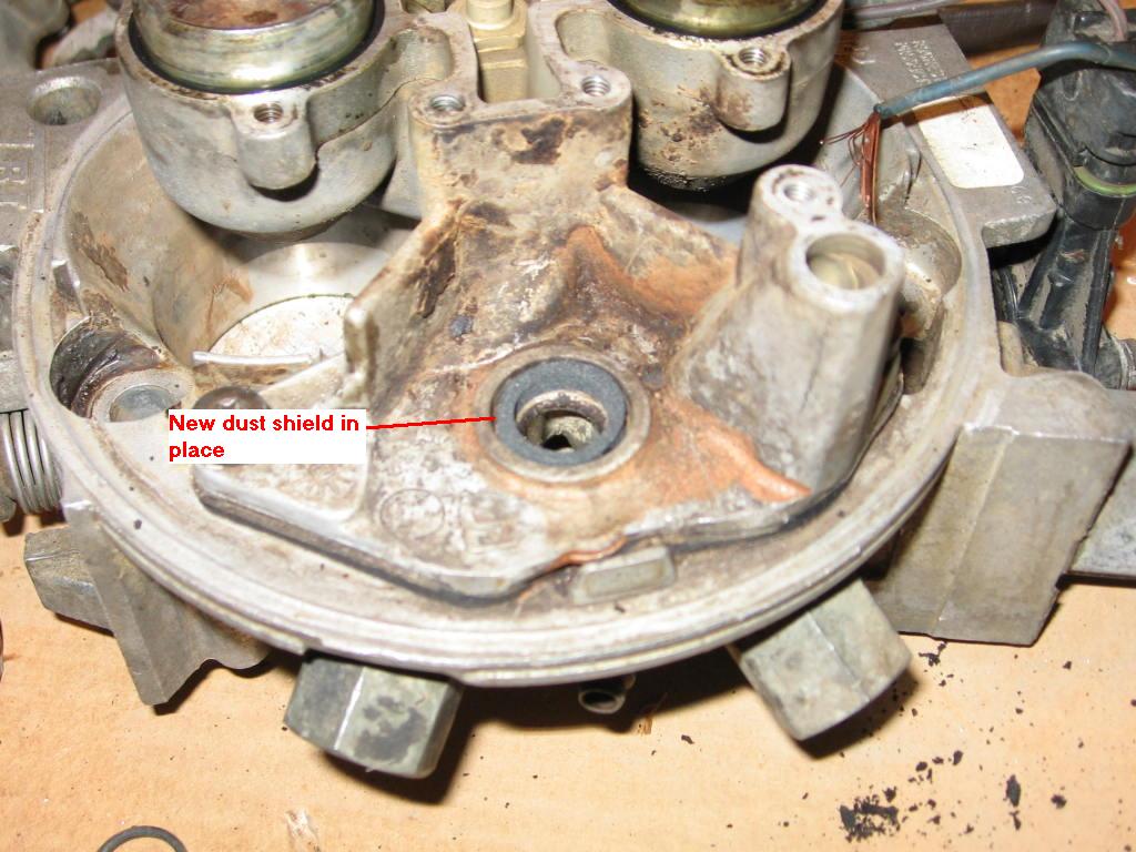
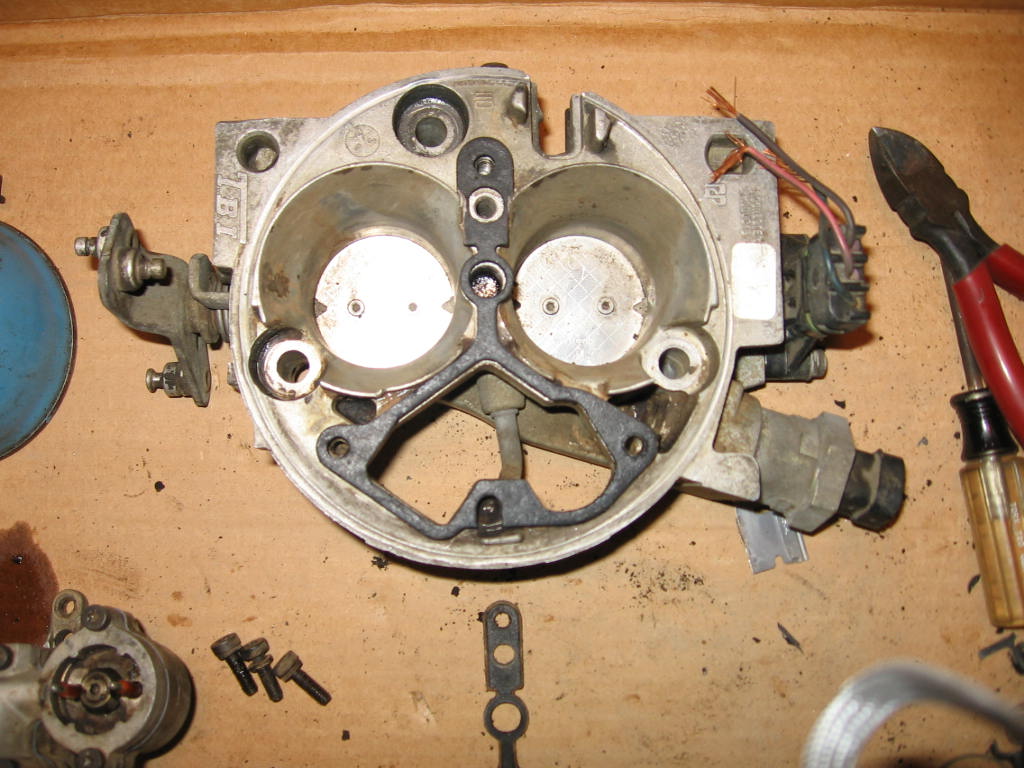
Both injectors are reinstalled. Now it is time to remove the Pressure regulator
dust seal. You will have to scrape it out, as it will be stuck in there from
age. |
|
|
|
|
|
New dust seal installed. |
|
|
|
|
|
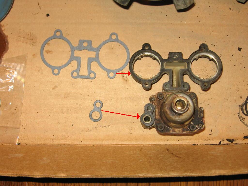
This is the fuel meter cover assembly placed upside down. The new gaskets go to
their respective areas. remove the old gasket with a razor blade. **Make
sure you don't score the area that the gasket sits on. The small gasket with
the 2 holes is for the fuel meter outlet. |
|
|
|
|
|
Now you are ready to reinstall the fuel meter cover assembly. |
|
|
|
|
|
Everything is back together. Tighten the bolts evenly, and go around tighten
each bolt a little at a time so you don't break the fuel meter cover assembly. |
|
|
|
|
|
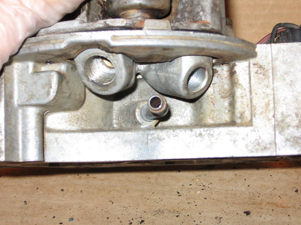
After you get everything on the top of the TB put back together you have to
replace the fuel meter body gasket. To get to this you must remove the fuel
inlet and outlet fittings. You can use an adjustable wrench to do this. |
|
|
|
|
|
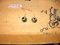
The fuel inlet and outlet fittings removed. |
|
|
|
|
|
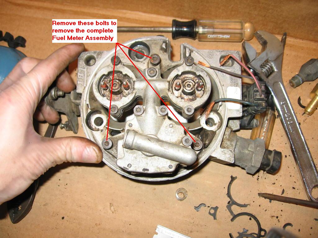
Next remove the 3 bolts that hold the fuel meter body to the throttle body
assembly. After the bolts are removed, gently lift the fuel meter body assembly
up off the throttle body assembly. |
|
|
|
|
|
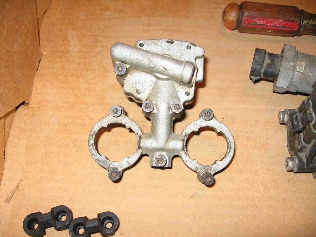
The fuel meter body removed from the throttle body. |
|
|
|
|
|
I had to trim the new gasket so that it fit like the old one did. |
|
|
|
|
|
Place the new gasket on and replace the fuel meter body on the throttle body. |
|
|
|
|
|
Put the new washers on the male end of the inlet and outlet fuel fittings and
place back on the throttle body assembly. |
|
|
|
|
Now that the throttle body is all back together you can put the gasket on the
throttle body that sits under the base of the air cleaner.
Now the TB has been rebuilt. |
|
|
|
|
|
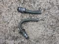
Save the hard lines and flanged connectors from the donor vehicle for later. |
|
|
|
|
|
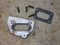
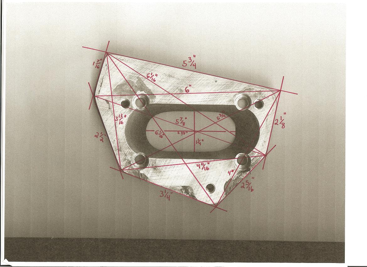
Step 4 Adapter plate for TBI to jeep intake |
|
|
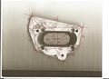
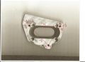
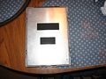
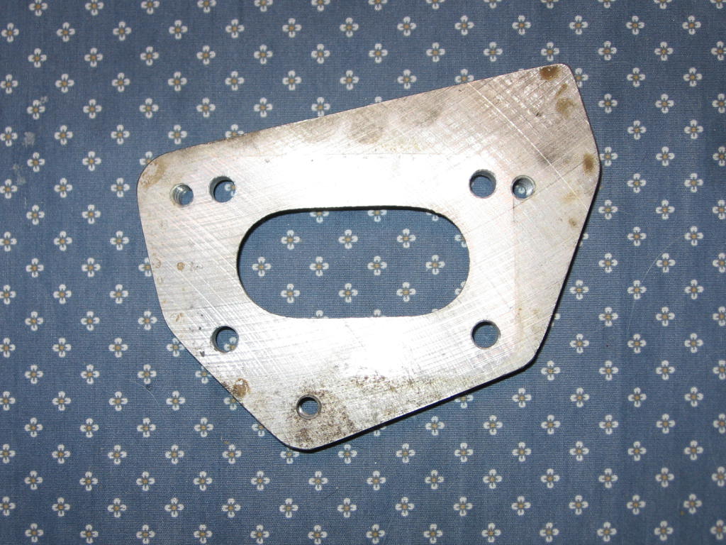
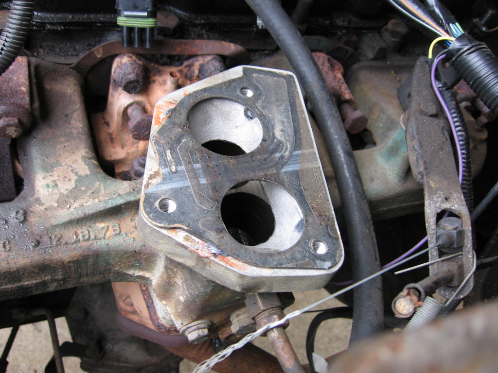
Here is one example of an adapter plate to mate the GM TBI unit to your Jeep 258
intake. A few things to note. First off, the plate doesn't have to
have these exact dimensions. What's important is the oval in the center
and the bolt holes surrounding it. The edges in this example are rounded,
but that's not a requirement either. Not the 4 holes near the larger
oval. The bevel edge of each hole facing the large opening should be
ignored. This plate is modeled after an aftermarket TBI kit and those
bevels will cause a vacuum leak unless filled with epoxy. |
|
|
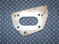
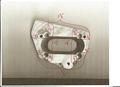
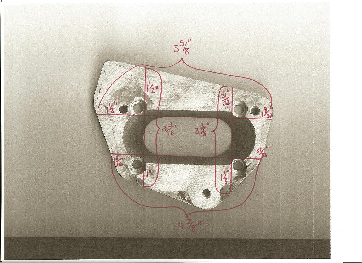
Here is a view of the bottom of the adapter. This plate is cut from
aluminum. The plate is 3/4" thick. Any metal fabrication shop could
duplicate it by just printing out the pictures. |
|
|
|
|
|
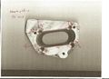
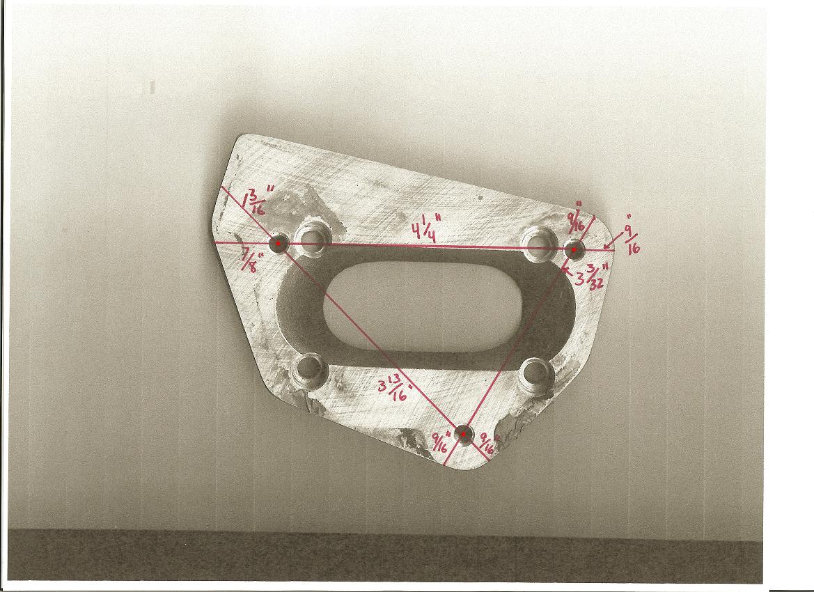
This picture gives more dimensions on the bolt holes. We'll be using Allen
head bolts to secure this to the intake manifold. |
|
|
|
|
|
This is a detail measurement of the large, inner hole.
Basically the injectors fire gas down this whole into the intake. |
|
|
|
|
|
Here are the measurements for the 4 holes surrounding the large intake hole.
Note once more, the bevels on all 4 holes as they point to the intake
hole...Do not duplicate these bevels. |
|
|
Here are three diagrams to help you build an adapter plate. |
|
|
AMC 258 w/ 1 barrel intake |
link
|
|
AMC 258 w/ 2 barrel intake (fuel lines facing rear) |
link
|
|
AMC 258 w/ 2 barrel intake (fuel lines facing front) |
link
|
|
|
|
|
Step 5 Trip to the parts store |
|
|
We need to get some new parts to make this project work. Here is a
breakdown and part numbers you'll need. |
|
|
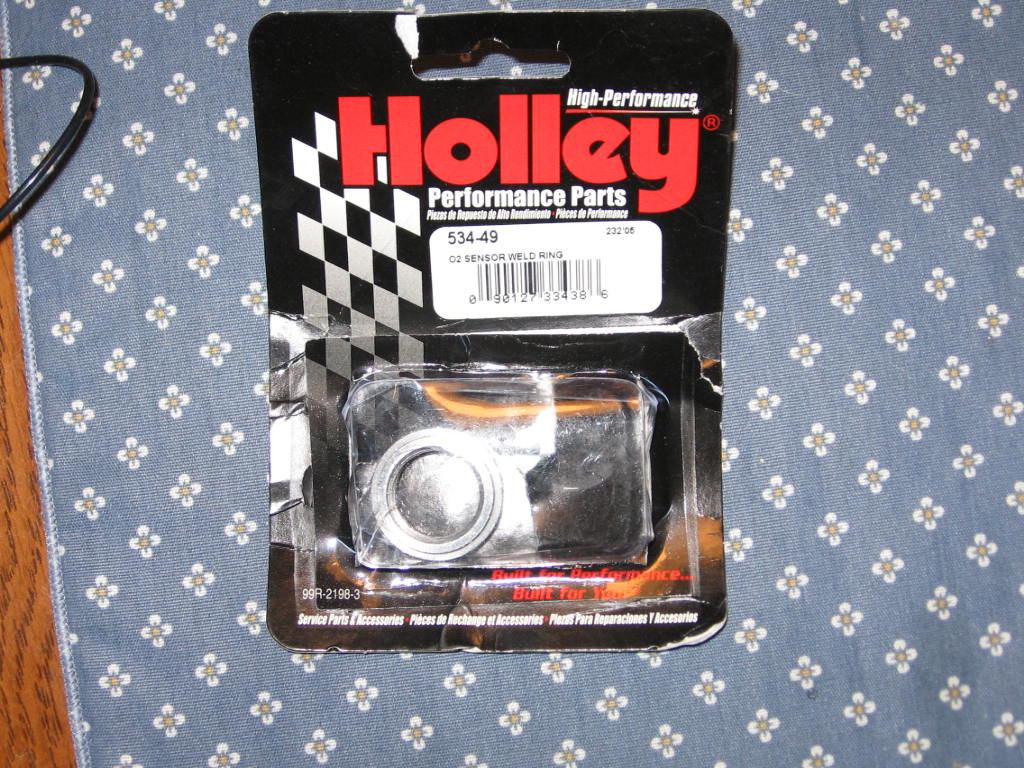
If you have an older jeep, you won't have an o2 sensor in the exhaust manifold
down pipe. You'll need to remove your front exhaust pipe, cut a
whole and weld this O2 Sensor weld ring Holley part #534-49 for the o2 sensor to
screw in to. Newer CJ/YJ's simply replace the stock o2 sensor with the new
one (see below) |

|
|
|
|
|
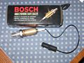
This is the o2 sensor we'll be using. Bosch 02 sensor part # 12014. |
|
|
|
|
|
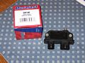
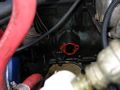
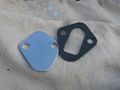
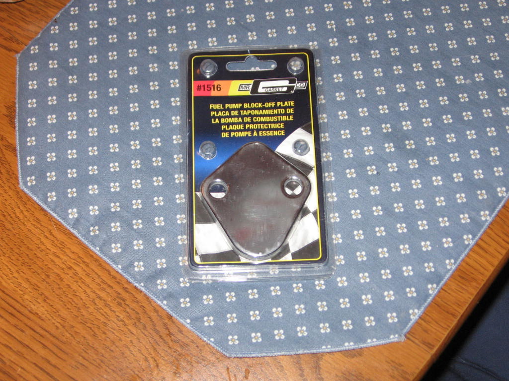
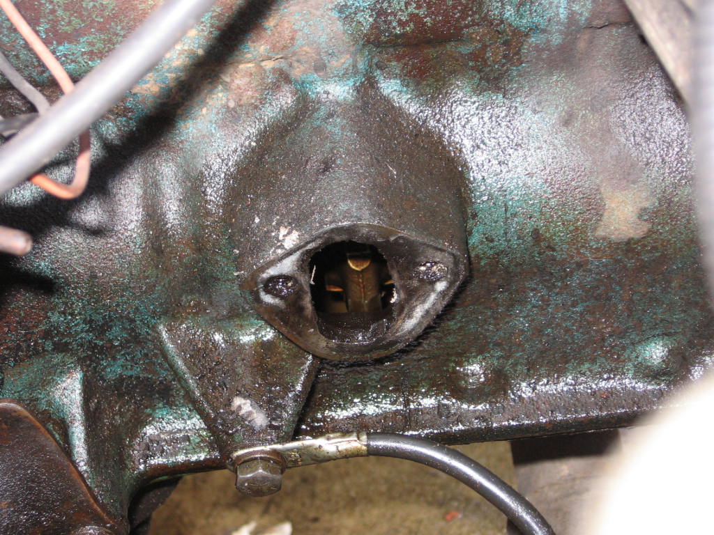
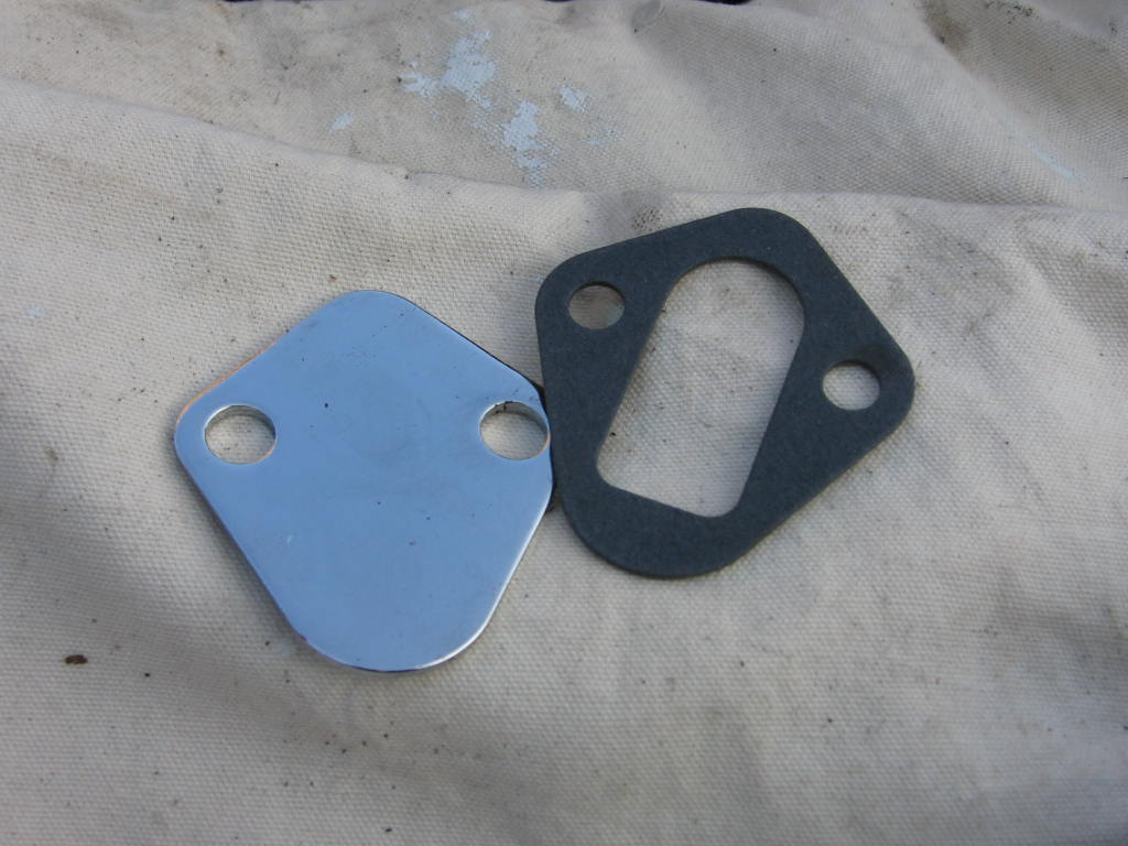
This upgrade requires the removal of your mechanical fuel pump in the block.
When we do this, we need to cover the hole in the block. Fuel pump block
off plate for a Chevy V8. This will fit the 258 fuel pump hole on the block.
Mr. Gasket part #1516. |
|
|
|
|
|
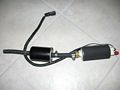
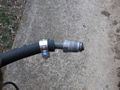
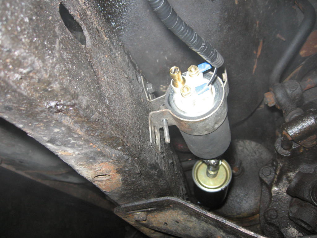
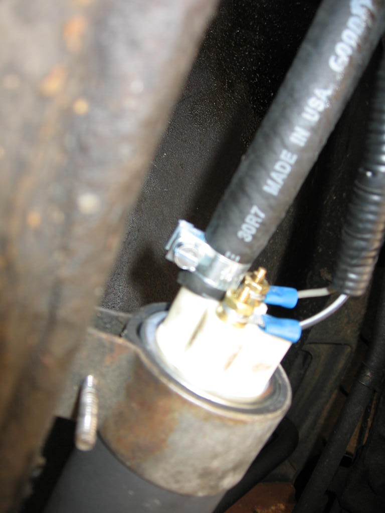
Fuel pump from Auto Zone Masters part # E2182 , we also purchased about 6' of
3/8" fuel line, and a fuel filter that would fit the line. Any filter should
work that will accept 3/8" fuel line. Assemble it as shown in this picture. |
|
|
|
|
|
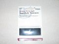
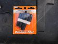
Conduct-Tite! part #85186 GM Throttle Position Sensor Socket. I had a '92 GM
harness and a pre'92 TB, I had to switch back to the old style TPS plug. I
picked up a new one at the local speed shop. |
|
|
|
|
|
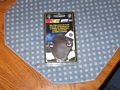
1-Pin Weathertight connector MSD Ignition part # 8174. I purchased this because
I cut the wire from the Chevy truck that had the factory connector for the O2
sensor. This way I know I will get a nice weather tight seal. I only needed
the female end of the connector because the O2 sensor has the male end already. |
|
|
|
|
|
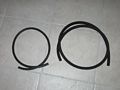
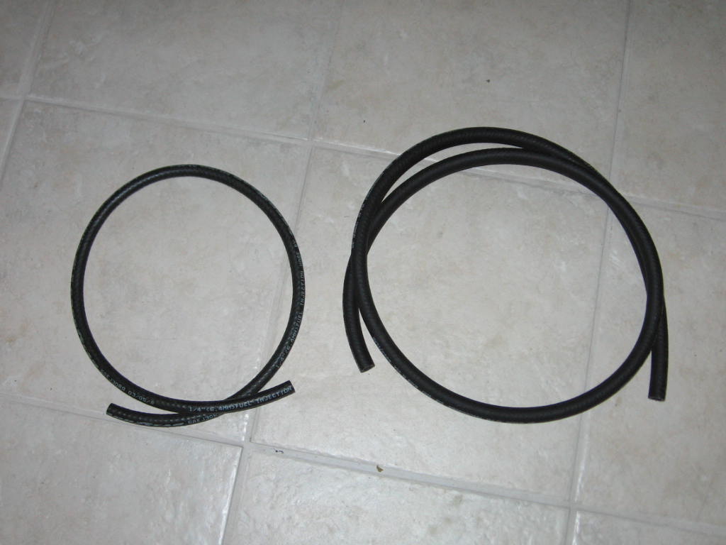
3' of 1/4" fuel line hose for the return line, and 6' of 3/8" fuel line hose for
the fuel supply line (about 1.5' will be used for the fuel pump) for the TB. |
|
|
|
|
|
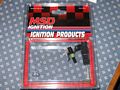
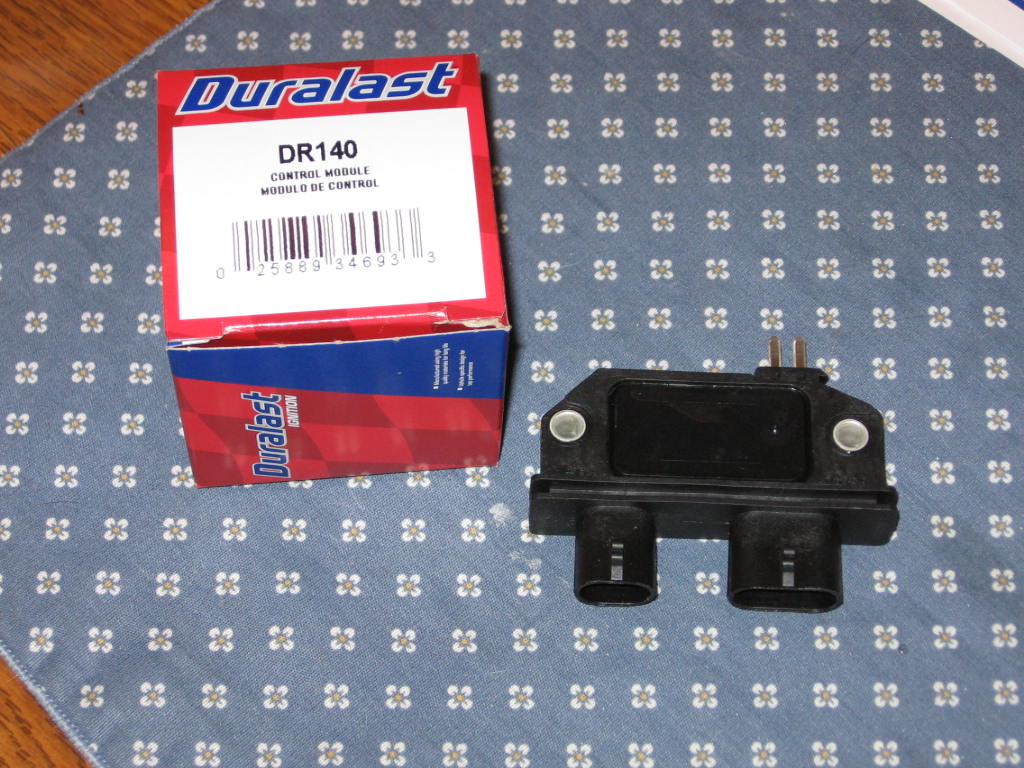
8-Pin GM Ignition Module (if you choose to have the ecm control timing too) Auto
Zone Duralast part # DR140. |
|
|
Step 6 Put it all together |
|
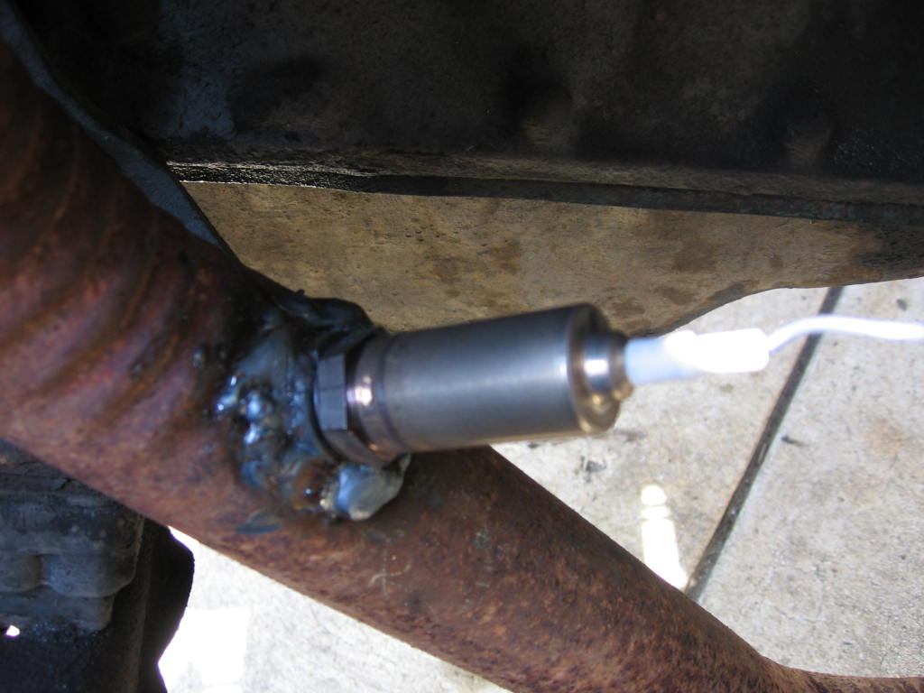
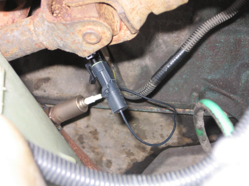
Now it's time to install the system. We'll tackle the sensors first.
Two sensors have to be installed on the engine, the temp sensor and the O2
sensor. The O2 was the hardest thing I'll have to do with this whole TBI
install. I am running a 79 258 in my CJ, so I had to weld an O2 sensor ring
into the exhaust. I just drilled a hole in the exhaust and welded the ring in
and installed the sensor. If you are running a pre-1980 258, you could
always take the front exhaust pipe off of the manifold and take it to an exhaust
shop to have this welded in. |
|
|
|
|
|
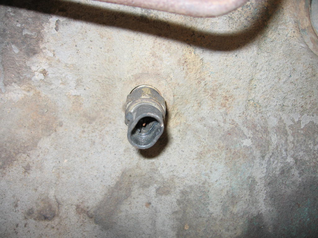
The next sensor on the block is the temp sensor. I installed it in the plug
that was on the driver side rear of the block, at piston #5 area. I just
removed the old plug and quickly installed the sensor so a lot of coolant
wouldn't leak out. The threads for the GM temp sensor and the plug are the same
so it will go right in. For newer 258 engines you need to simply swap the
new sensor in for your old one (see second pic) |
 |
|
|
|
|
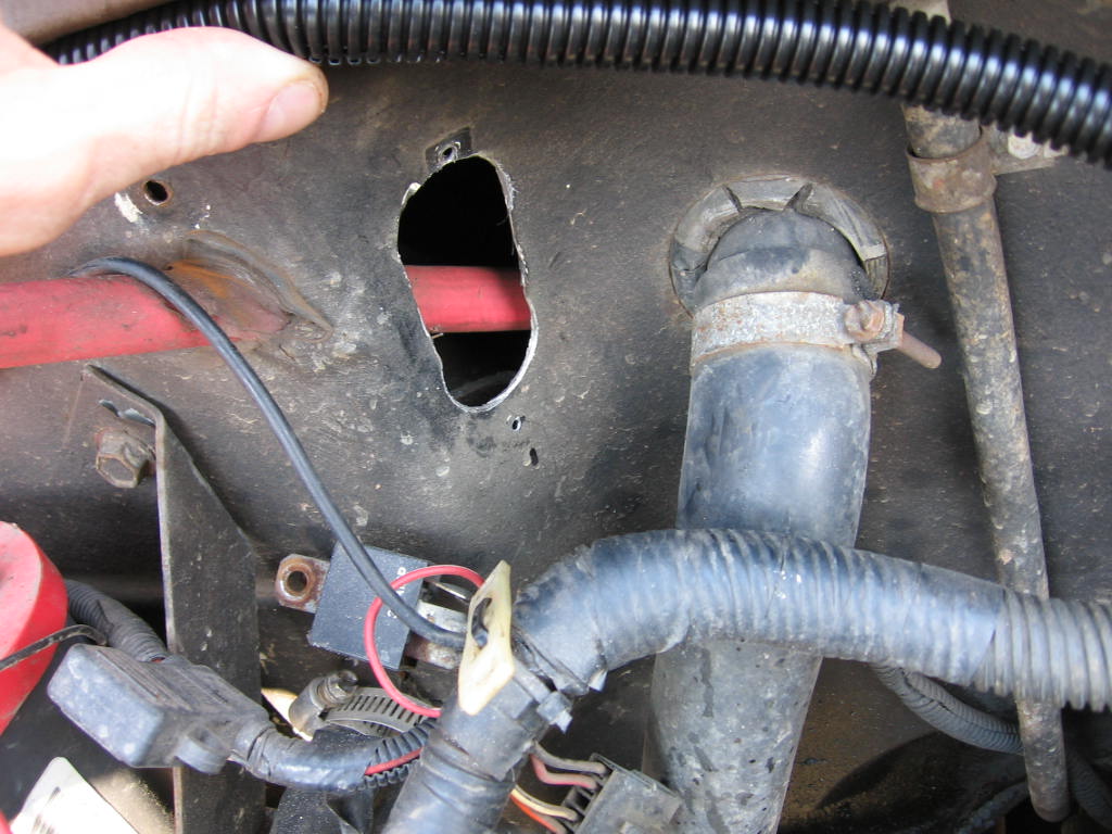
Making a hole in the firewall for the wiring harness. (Let me explain here, my
CJ originally is an 84, I swapped a 79 tub that was in better shape onto my
frame so I didn't have a hole in the firewall, but I had an 84 CJ harness so I
used the grommet, and made a hole to accommodate that in the 79 tub.) I used a
1 1/8" hole saw to make 2 holes that would allow the CJ wiring harness grommet
to fit, and cut out the excess sheet metal in between with a cut off wheel.
Those of you with newer 1980's CJ tubs will only need to cut the stock grommet
to fit the thicker wiring through (see third pic)
|
 |
 |
|
|
|
|
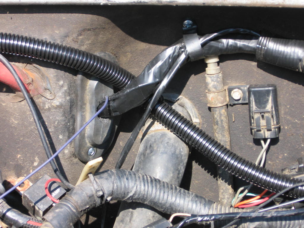
Here is the TBI harness installed in the CJ with the use of the factory 80's CJ
wiring harness grommet. To use the grommet you have to cut one side down to the
hole in the center, and then bend it open. There is an outer metal ring in it
that allows it to bend and stay rigid. After you bend it open, put the new
harness into it and then close it back up. You may have to remove some rubber
from the center because the TBI harness is a little thicker than the CJ factory
harness. After the TBI install is complete you can go back and silicone the
grommet to make sure all moisture will stay out.
|
|
|
|
|
|
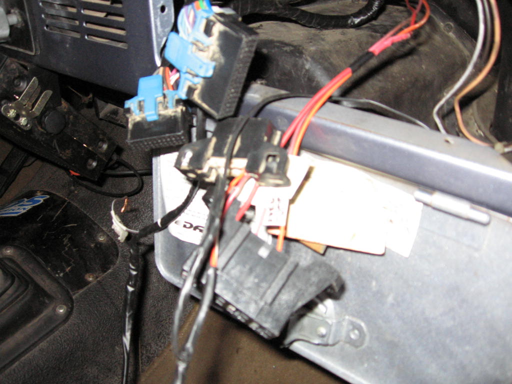
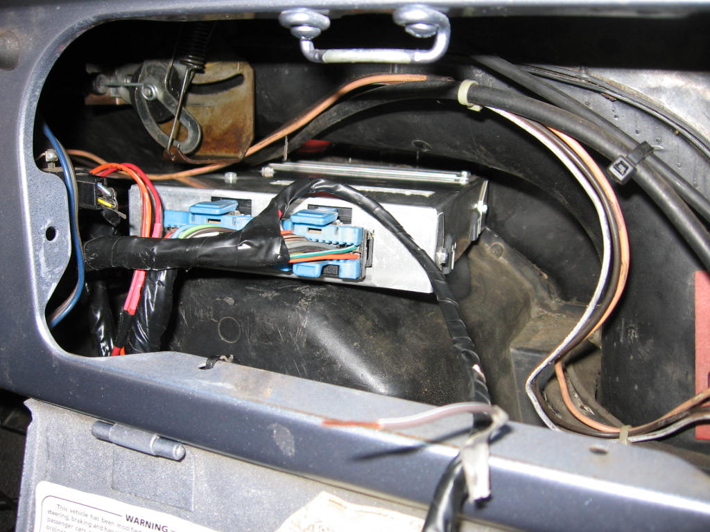
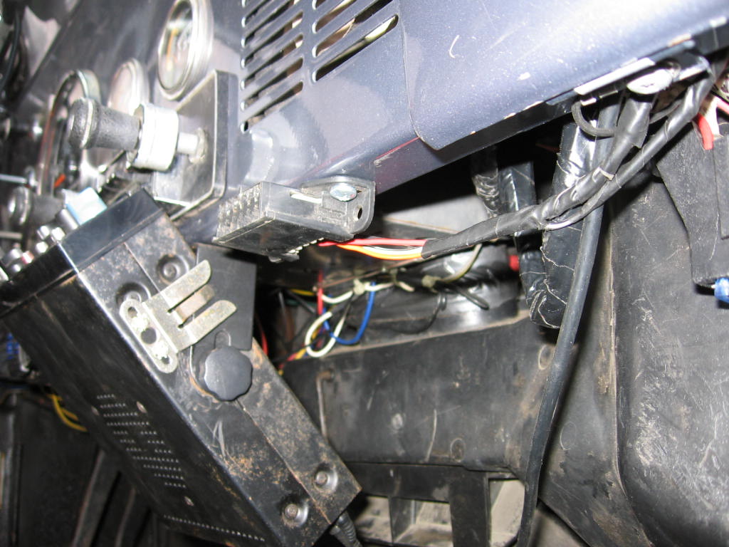
This is the wiring that will be inside the jeep. Its the 2 ECM plugs, the ALDL
plug, and the fuseblock. |
|
|
|
|
|
Layout the harness so that the wires are where they are supposed to be and then
mount the harness to the firewall. I used a few plastic 1" clips and self
tapping screws to attach the harness to the firewall. |
|
|
|
|
|
Mount the fuel pump relay and fuse to the firewall. |
|
|
|
|
|
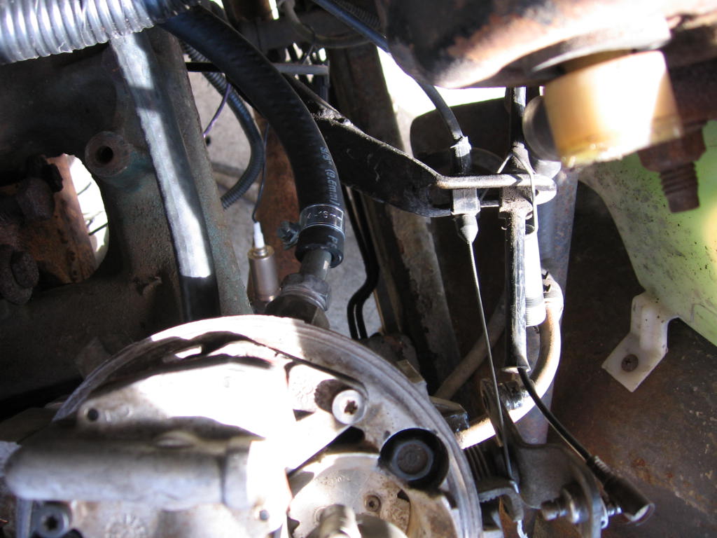
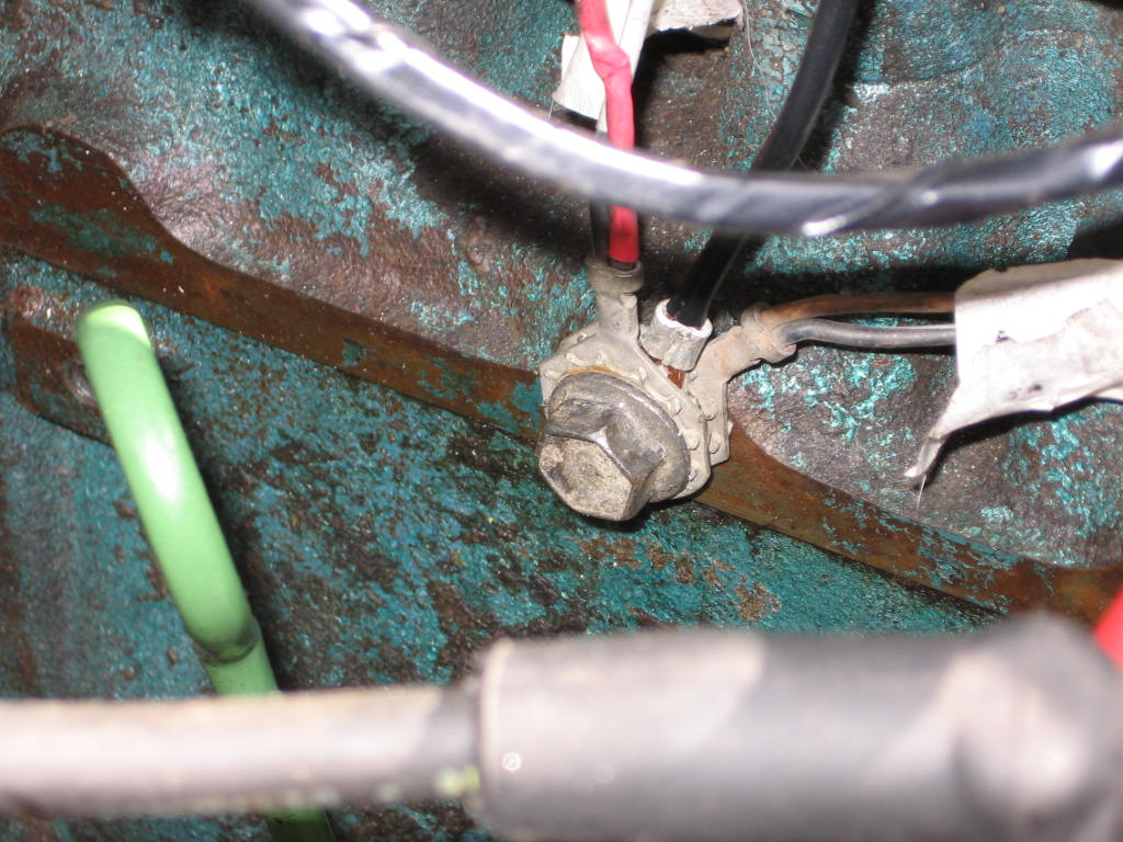
I decided to move to the fuel pump next.
** Before I disable the engine, first I set the timing to 0 because I
need it to be there for the ECM controlled spark.
First remove the old fuel pump and hoses. Remove the rubber fuel return
line from the hard return line. |
|
|
|
|
Remove the fuel supply line from the carb. (I'm running a 2100 before the TBI)
|
|
|
|
|
Remove the rubber supply line off of the fuel pump which is located on the
passenger side of the block.
|
|
|
|
|
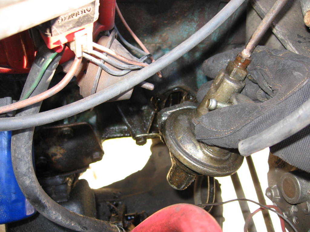
Now remove the fuel pump. It is held in place by 2- 1/2" bolts. Just remove
the bolts and pull the fuel pump out.
|
|
|
|
|
|
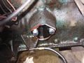
After you remove the fuel pump from the block, thoroughly clean the gasket
surface to prepare it for the fuel pump block off plate. |
|
|
|
|
|
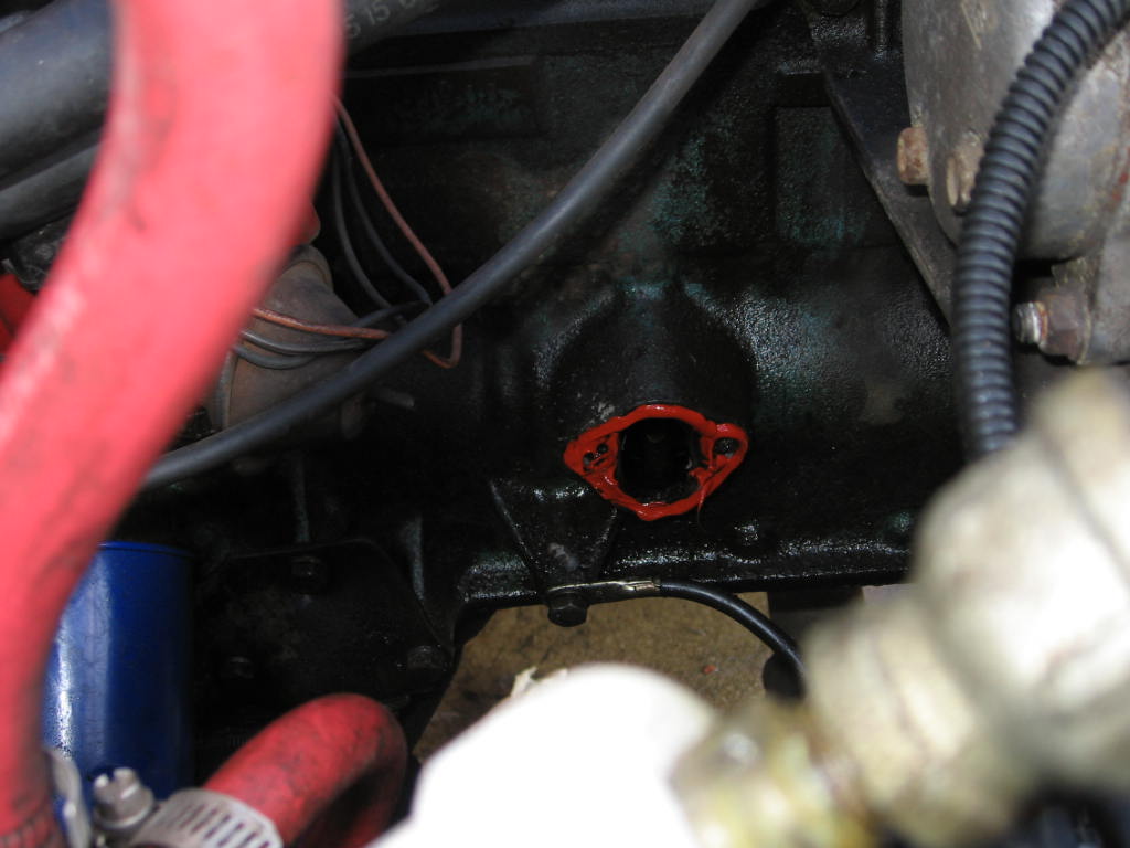
To install the fuel pump block off plate you will need to get some shorter bolts
than the fuel pump used. Then put RTV around the fuel pump block off plate and
let it setup, then install it on the block. |
|
|
|
|
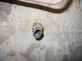
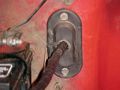
Installed fuel pump block off plate.
|
 |
|
Step 7 The fuel pump |
|
|
|
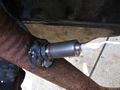
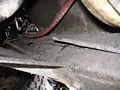
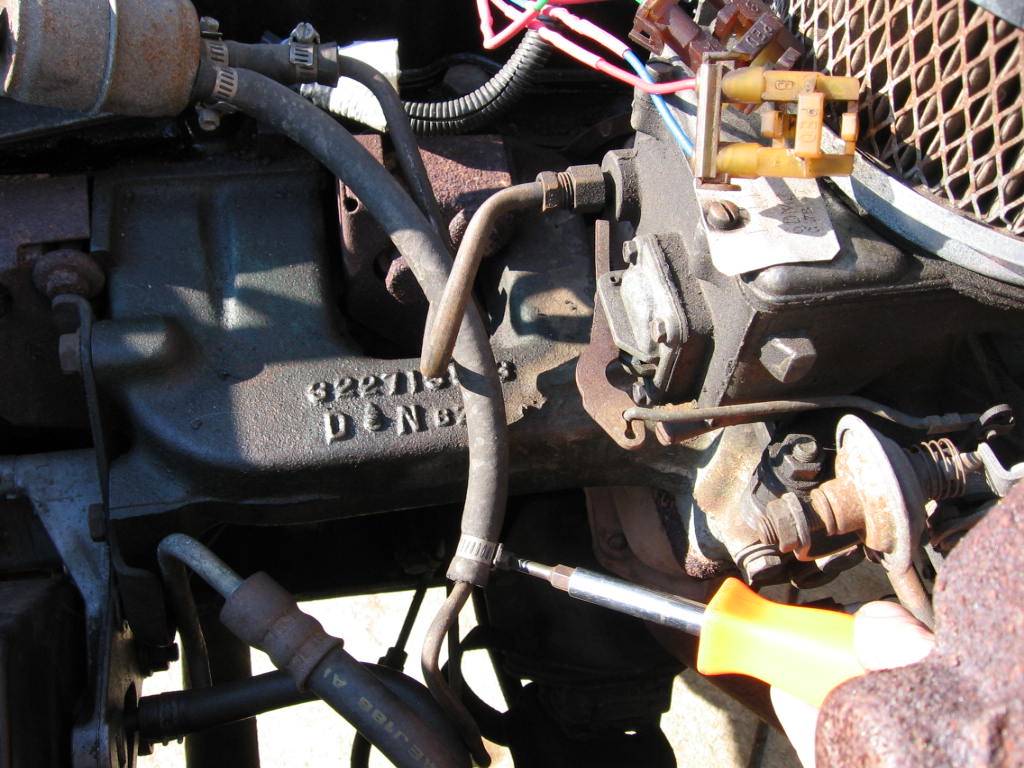
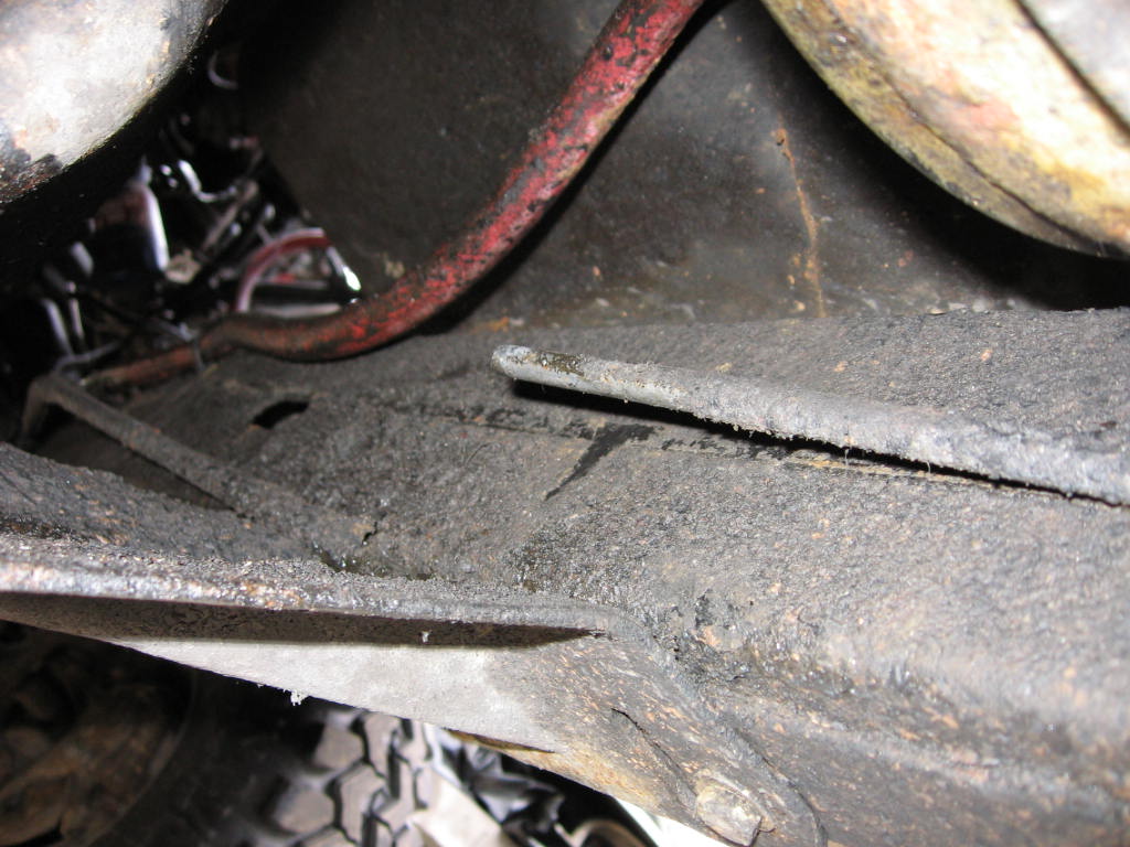
To install the fuel pump you will have to cut the hard line. I used a small
pipe cutter. The hard line was cut just over the the t-case skid. |
|
|
|
|
|
Before you cut the hard fuel line pinch the rubber hose close to the gas tank
with a pair of vise-grips to prevent fuel from running out. |
|
|
|
|
|
After you have the hard line cut, unbolt the hard line from the passenger side
motor mount bucket. You will also need to unbolt the hard line right under the
front of the tub on the frame. This bolt can be reused to hold the fuel pump in
place. |
|
|
|
|
|
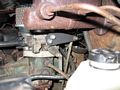
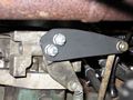
Mount the Fuel pump and filter to the frame. You can see the bolt in the frame
that holds the pump in place. It was the bolt that previously held the hard
line to the frame. To mount the fuel pump to the frame I used an old stock
ignition coil bracket. |
|
|
|
|
|
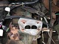
Step 8 Mounting the TBI unit to the intake |
|
|
|
|
|
Remove the carb from the intake manifold. |
|
|
|
|
|
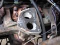
|
|
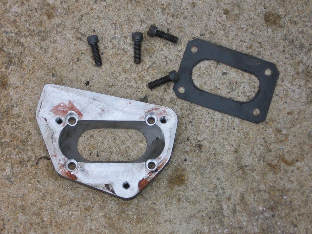
This is the adapter plate, bolts and lower gasket that I will be putting on the
intake. |
|
|
|
|
|
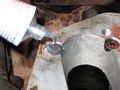
|
The adapter plate installed on the intake. |
|
|
|
|
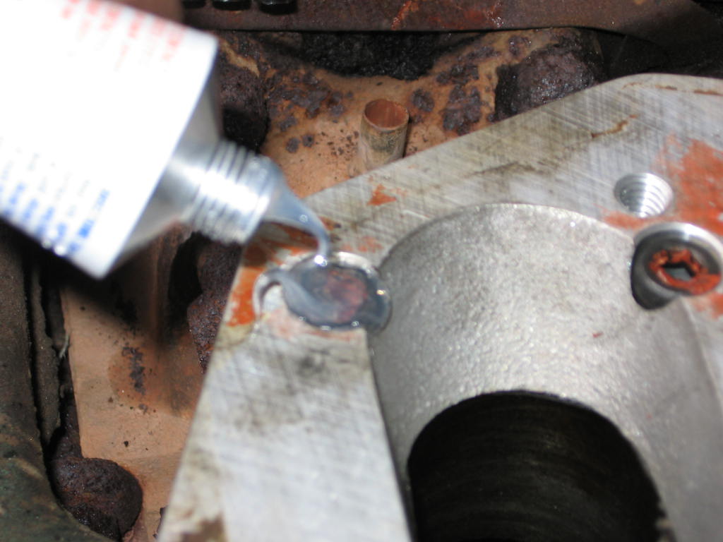
I am using an original Howell adapter plate. I have top use silicone to seal
the top of the mounting bolts so there aren't any vacuum leaks. The new Howell
adapter plates don't have this problem.
|
|
|
|
|
|
Place the TB gasket on the top of the adapter plate |
|
|
|
|
|
Install the TB on the adapter plate. The TB bolts were 1/2" hex head. |
|
|
|
|
|
To connect the fuel supply and return lines to the TB I used the hard lines from
the donor vehicle, and cut them with a small pipe cutter to get them to the
desired length. |
|
|
|
|
|
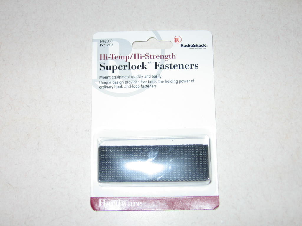
I picked up some Dual Lock from RadioShack. I used it to mount the ECM and the
fuse block for the TBI. |
|
|
|
|
|
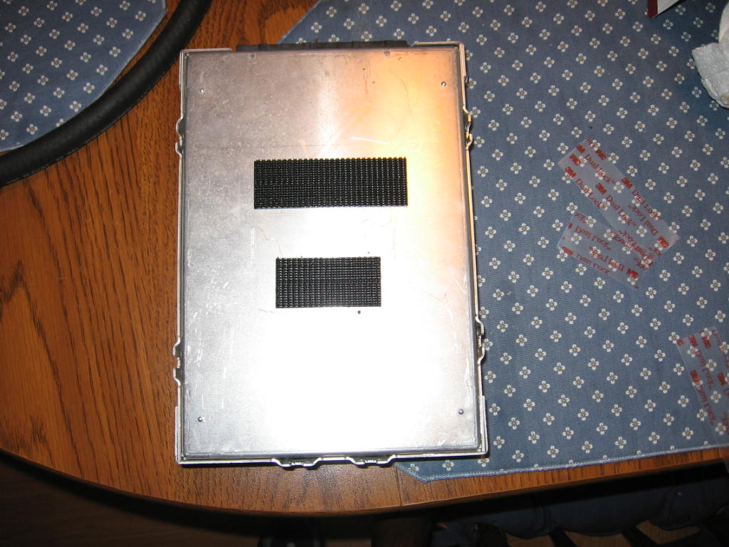
Place the Dual Lock on the back of the ECM and then mount the ECM on the top of
the heater box. Clean the top of the heater box so it sticks. |
|
|
|
|
|
Plug the wiring harness into the ECM. |
|
|
|
|
|
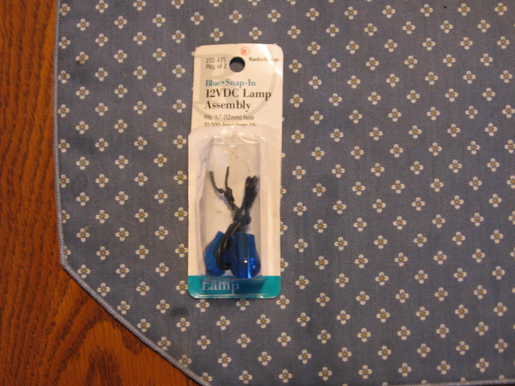
I picked up a 12v lamp from RadioShack for the SES light. one half of the lamp
connects to the SES wire from the ECM (that is a ground), and the other goes to
a hot that is powered when the key is in the on and run position. |
|
|
|
|
|
Mount the ALDL connector. |
|
|
|
|
|
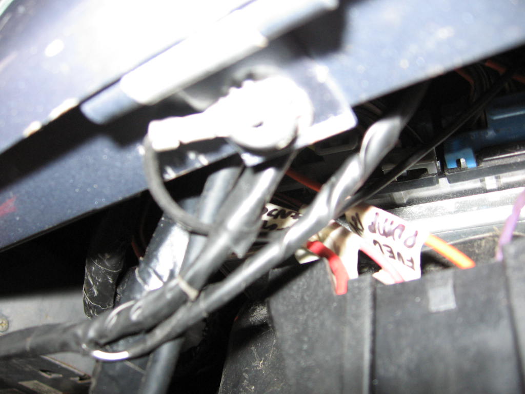
Sorry for the blurry shot, I had a ground wire for the ALDL that I needed to
connect near where the ALDL plug was. I could have spliced this into any other
ground in the harness but decided to give the plug its own. |
|
|
|
|
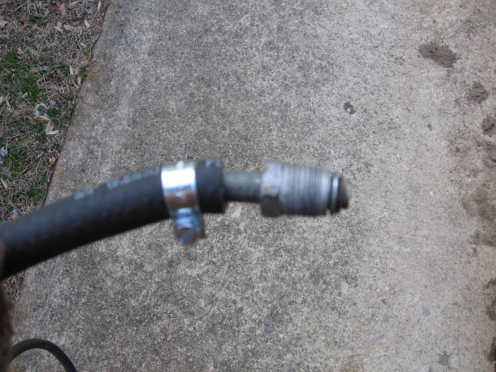
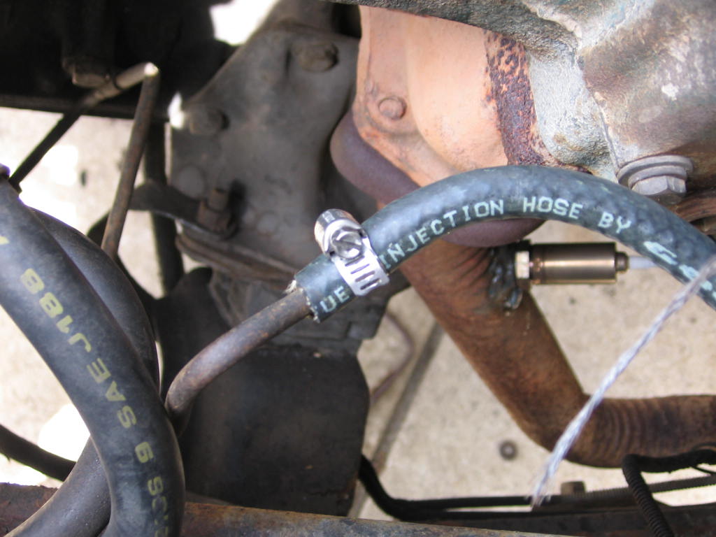
Put the fuel supply hard line (remember we saved that earlier?) into the rubber
line and use a fuel injector clamp to hold it in place.
|
|
|
|
|
Attach the supply line to the rear of the Throttle body. The fuel supply
line goes to the driver's side inlet on the Throttle body.
|
|
|
|
|
Attach the other side of the supply line to the fuel pump.
|

|
|
|
|
Put the return hard line into another rubber line and use a fuel injector clamp
to hold it in place. Attach this to the other port on the back on the
Throttle body.
|
|
|
|
|
Attach the other side of the return line to the metal return line that goes to
the block then back to the tank.
|
|
|
|
|
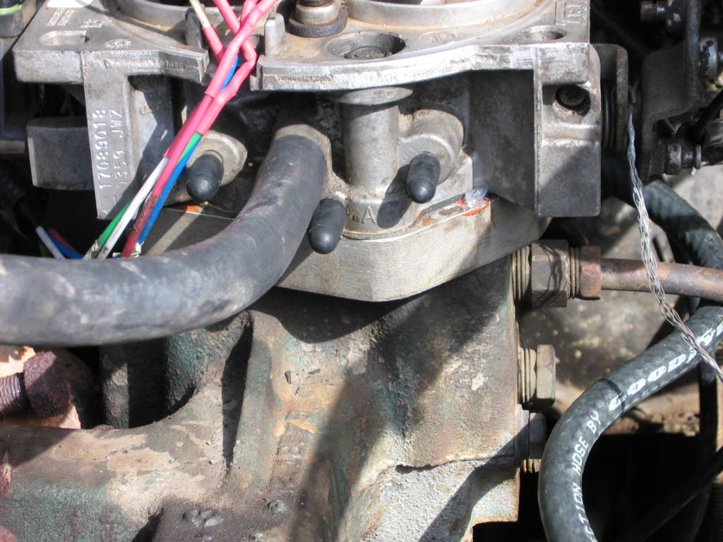
Use vacuum test plugs to cover the vacuum holes you won't be using.
|
|
|
|
|
Put the test plugs on the TB. That one vacuum line you see (the big one)
goes to your PCV valve on your valve cover.
|

|
|
|
|
Plug the O2 sensor into the main harness.
|
|
|
|
|
|
Attach the grounds to the block, or you can use a junction block that goes
directly to the battery. |
|
Step 9 Electronically controlled spark (HEI) |
|
|
|
Here are directions on how to set up a large cap HEI distributor to work with
the TBI setup. I am going to fully computer controlled spark, so the vacuum
advance has to be removed and the pickup needs to be secured to the base of the
dist. The mechanically advance also has to be locked in place (tack welds
work). Nothing inside the Dist can move as the ECM will control all the
timing. To do this You need to go to a 7 or 8 pin GM ignition module. Through
research I found the 8 pin is easier to hook up, as it came on the vehicle that
the TBI, ECM and harness came from. |
|
|
|
|
|
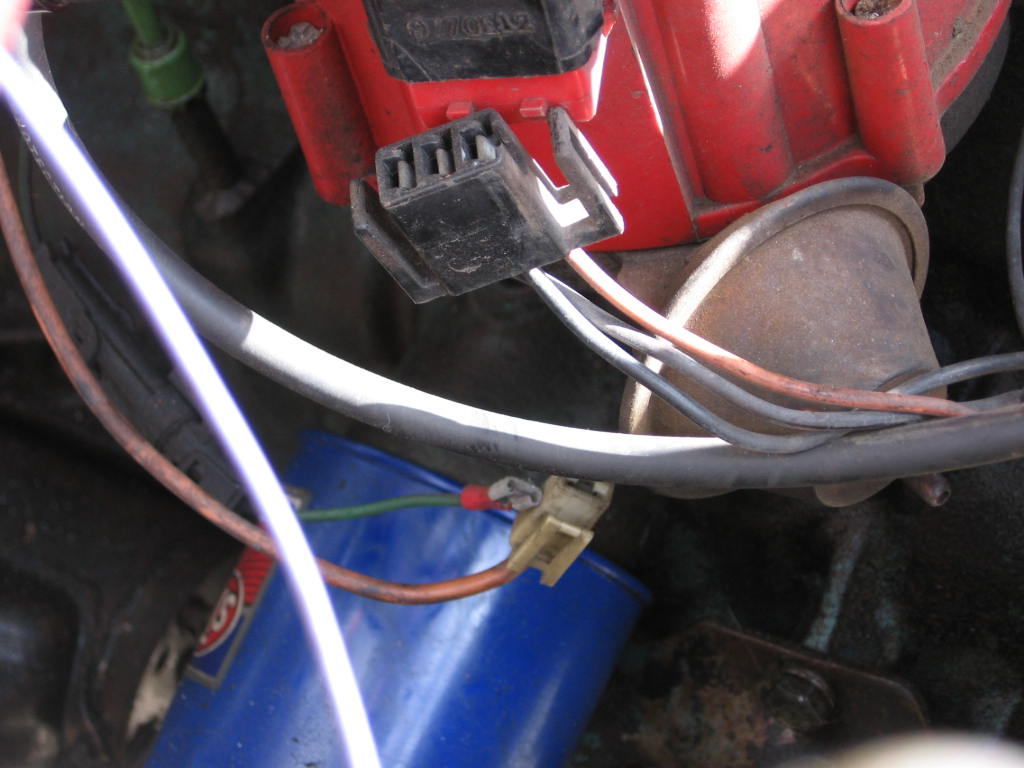
Remove the power, tach, and ignition module connections from the cap. |
|
|
|
|
|
Remove the distributor cap. |
|
|
|
|
|
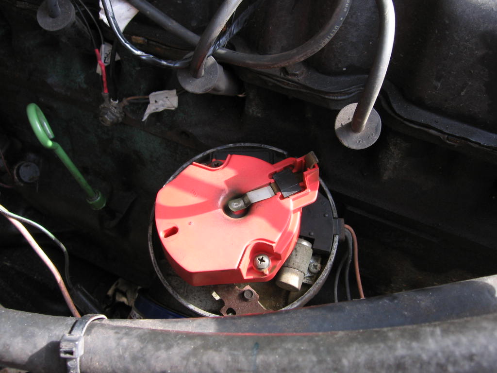
Remove the rotor. |
|
|
|
|
Remove the springs, weights, ignition module, condenser pack, and vacuum
advance. The pickup wire (white and green will be the only thing left in the
dist.
|
|
|
|
|
Drill a hole in the base of the dist, so you can lock down the vacuum advance
with a long self tapping screw.
|
 |
|
|
|
|
|
Open the condenser pack. You can leave the ground end on, but you will have to
cut the brown and orange wires. |
|
|
|
|
|
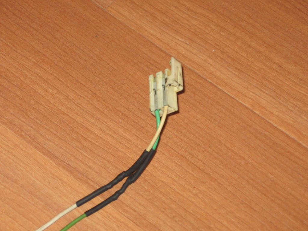
Make a harness to connect the 3 prong plug from the condenser pack, to the 8 pin
ignition mod. The other harness (green and white) is made up of 2 spade
connectors on the one end to connect into the pickup on the HEI dist, and the
other end is the plug that goes to the P and N pins of the 8 prong GM ignition
mod. I pulled the plug from the distributor on the junkyard engine. |
|
|
|
|
|
Pickup coil plug that goes to the ignition mod from the junkyard engine. |
|
|
|
|
|
This is the other plug that goes to the 8 pin GM ignition module. It should
come with the harness you get from the donor vehicle. |

|
|
|
|
I tack welded the mechanical advance so it would not move since I was doing the
computer controlled spark. The ECM will adjust the timing now.
|
|
|
|
|
Everything is hooked up to the dist. The wires to the pickup go to the ignition
module, the black goes to the ground on the dist, and the 3 prong plug that
connects to the cap of the HEI (coil + and -) go to the ignition module also.
|
|
|
|
|
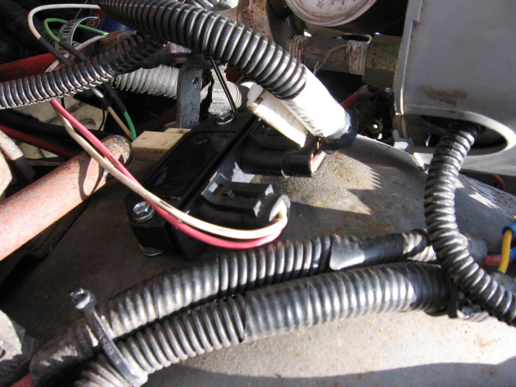
Here is the 8 pin GM ignition module mounted on the fender. Be sure to ground
the back of the ignition module (there's a shiny mounting surface). The white
and green are the dist pickup, the red and white go to the orange and brown that
originally connected to the condenser (orange to res, brown to white). The last
plug is made of 4 wires. They are the EST wires that go to the ECM.
|
|
|
|
|
|
Here is a close up of the GM 8 pin ignition module. The plug on the bottom
right is the 4 prong EST wires from the TBI harness, the plug on the bottom
left is the coil + and -, and the 2 bare pins on the top right are for the
pickup coil. |
|
|
|
|
|
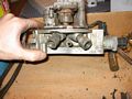
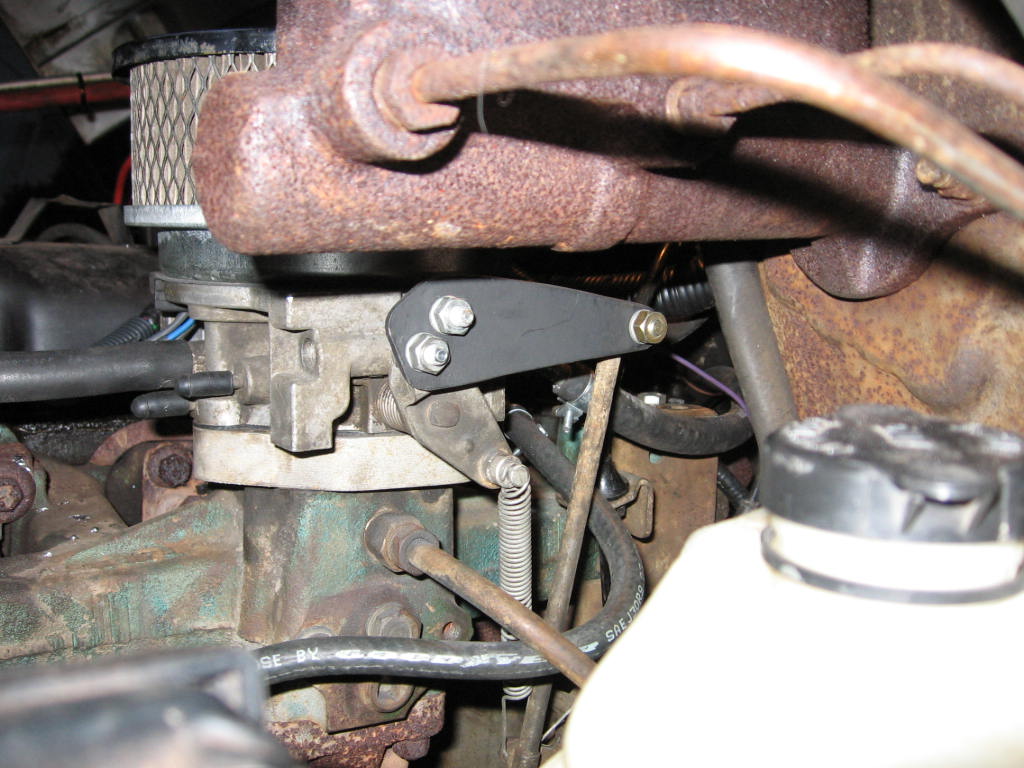
I was having some trouble with the fabricated throttle bracket that the PO of my
engine made. It pulled directly back. I wanted to go back to the stock CJ
bracket that pulled downward with a bell-crank setup. I ended up making a lever
arm for the throttle body out of 1/8th" steel, so that the stock bracket could
be used. |
|
|
|
|
|
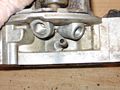
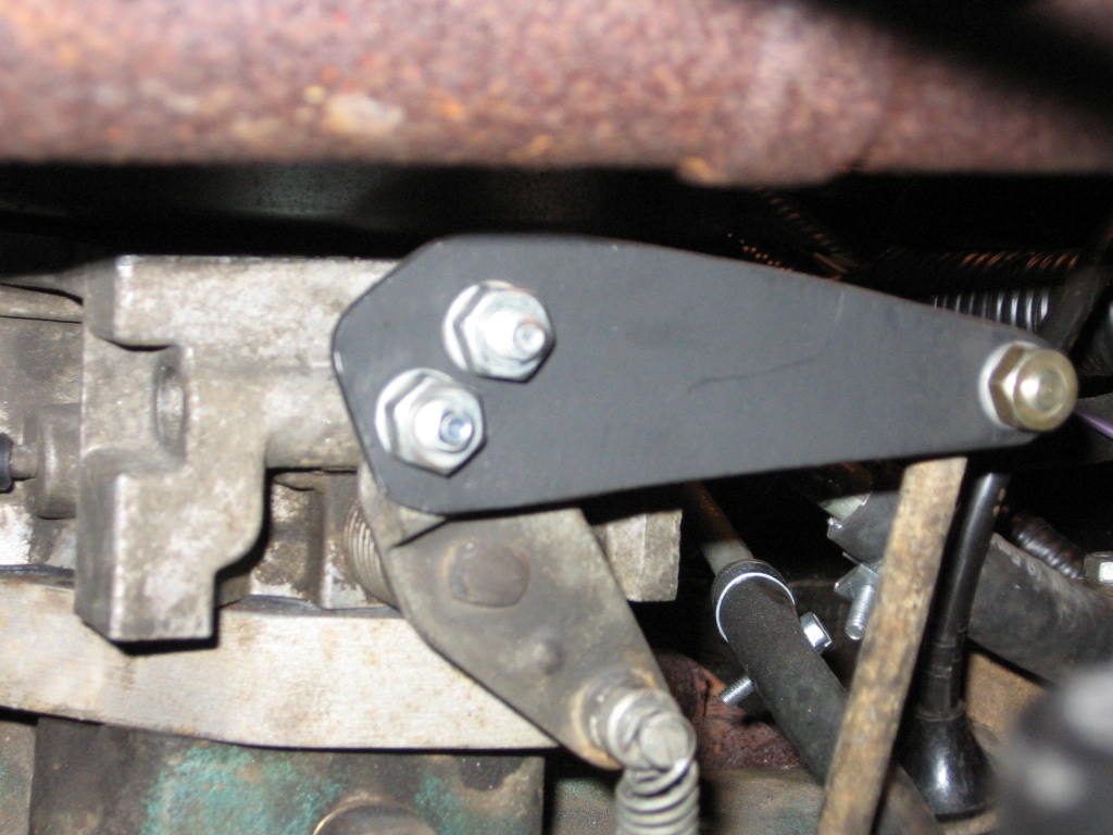
I removed the factory throttle body cable attachments (gm uses a clip to keep
the cables on) which left me with 2 holes that I used to bolt the lever arm to
the throttle body. I then placed a throttle cable ball that I got from the
local speed shop (it was a Holley assortment set) to attach the throttle bracket
arm. |
|
|
|
|
|
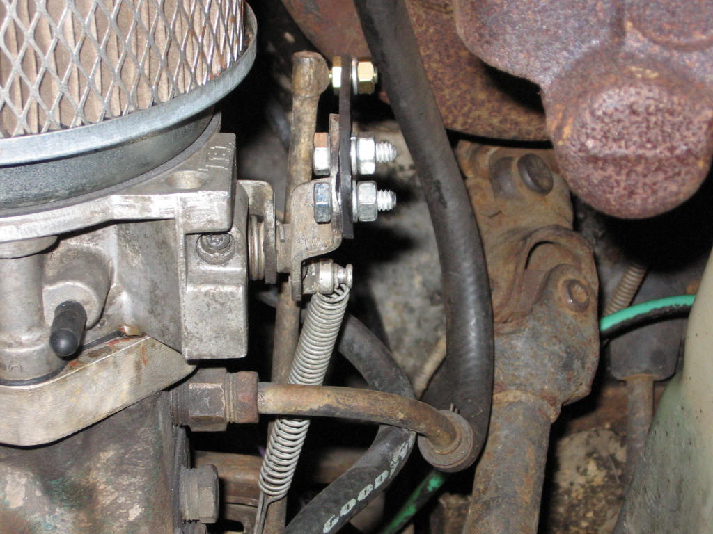
After that I used a spring that I had for the old carb to help with the throttle
return. I could have left it alone but I like the pedal to be a little firmer
than the throttle body spring made it. |
|
|
|
|
|
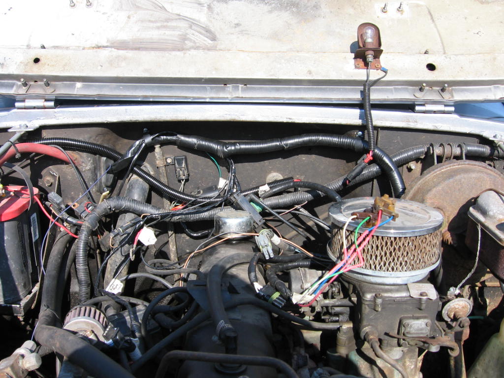
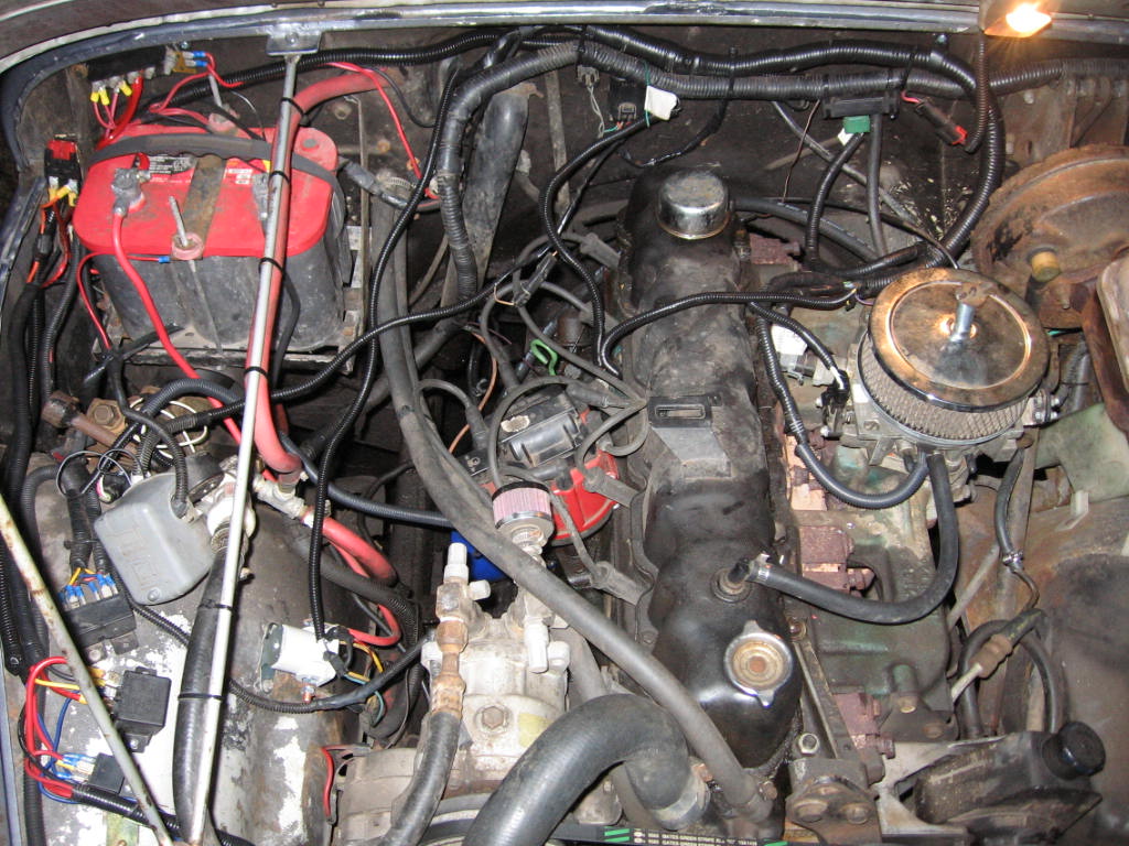
Here is the completed TBI system on the engine. I cleaned all up the wires with
split loom to make it look good. there are a few wires going to the passenger
side fender. That's where I put the GM 8 pin ignition module. I am going to up
grade the air filter too so I have it rigged right now to fit the filter that
was on my 2100 carb. The rod that comes with the TBI seems to long, so I will
bend up some all-thread to work in its place. |

|
|
|
|


